Quick Installation Guide
Wireless Access Point
Setup with videos
Visit https://www.tp-link.com/support/setup-video/ or scan the QR code
to search for the setup video of your product model.
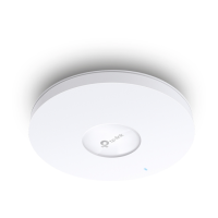
Note: EAP650 is used as an example throughout the Guide. Images may dier from the actual product.
Hardware Overview
1
RESET
With the device powered on, press and hold the button for about 5 seconds until the LED flashes quickly. Then
release the button. The device will restore to factory default settings.
Ethernet Port: ETH (PoE)
The port is used to connect to a router or a switch to transmit data, or to a PSE (Power Sourcing Equipment),
such as a PoE switch, for both data transmission and Power over Ethernet (PoE) through Ethernet cable.
Note: For EAP770, if you use a CAT5E cable, the 10Gbps link of the Ethernet port is less than 55m. To achieve a longer transmission
distance, use a shielded CAT6A cable.
Power Port
Plug one end of the power adapter to this port and the other end to a standard electrical wall outlet to power the
E AP.
Note: Power adapter is not included in the package contents of EAP653 and EAP613. For power supply specications, please refer to
the label at the bottom of the product.
Self-tapping Screws
Plastic Wall Anchors
1
Remove the ceiling tile.
Note: Make sure that the ceiling tile is larger than the EAP.
Wing NutsWashers Pan-head Screws
The EAP can be mounted to the ceiling, the wall, or in a junction box, using the screws in the
package. Choose the appropriate mounting and installation steps below.
Note: This product requires heat dissipation through the metal bracket during use, please be
careful not to touch the metal bracket in the heat dissipation.
Hardware Installation
2
2
Insert the plastic wall anchors into the 6 mm
diameter holes.
4
Connect the Ethernet cable to the Ethernet
port on the EAP.
Front Panel
Rear Panel
Option 1: Ceiling Mounting
Option 2: Wall Mounting
5
Connect the Ethernet cable to the Ethernet port.
Please pay attention to the triangle sign. Attach
the EAP to the mounting bracket, then rotate it
until it locks into place, as shown on the left.
2
Place the mounting bracket in the center of the
ceiling tile. Mark positions for the screw holes
and a location for the Ethernet cable hole.
Drill 4 mm (5/32 in) diameter holes for the screws
and a 25 mm (63/64 in) diameter hole for the
Ethernet cable at the marked positions.
Drill Hole for Ethernet cable
X4
3
Secure the mounting bracket to the ceiling tile
using pan-head screws, washers, and wing nuts,
as shown on the left.
5
Attach the EAP to the mounting bracket by
rotating it until it locks into place, as shown on
the left.
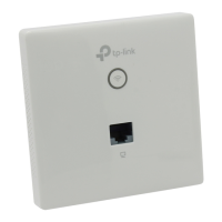
Option 3: Junction Box Mounting
4
Feed the Ethernet cable through the hole and
set the ceiling tile back into place.
Prepare the cables and the junction box in advance. Ensure that the mounting holes align
to your junction box.
*Compatible wall junctions:
Route the cables through the square cable
hole on the mounting bracket, and secure the
mounting bracket to the junction box using
screws. Then follow Step 4 and Step 5 of
Option 2 to complete the installation.
3
Secure the mounting bracket to the wall by
driving the self-tapping screws into the
anchors. Make sure that the shoulders of the
mounting bracket are on the outside.
1
If your Ethernet cable feeds through the wall,
position the mounting bracket below the cable
hole. Mark positions for the screw holes and
drill 6 mm (15/64 in) diameter holes at the
marked positions.
X4
Option 2: Wall MountingOption 1: Ceiling Mounting Option 3: Junction Box Mounting
Blue On:
Working normally/Initializing. For EAP770: Normal power supply (12V DC/802.3bt)
Orange On:
For EAP770: Low power supply (802.3af/at)
Flash: • Flash twice:
Initialization is completed.
• Flash quickly:
The EAP is resetting, or the Omada controller is locating the device*.
• Flash once per second:
The EAP is upgrading.
• Flash Slowly:
The EAP is in the isolated state.
LED Indicator
Off:
Working abnormally/Power o/LED is turned o.
* When the Locate feature is activated in the Omada controller, the LED ashes quickly to locate and identify the
device. The LED will ash for 10 minutes. You can disable the feature manually to stop it from ashing.