Do you have a question about the TP-Link Omada and is the answer not in the manual?
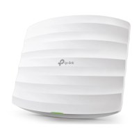
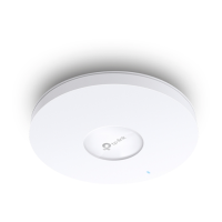
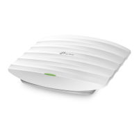
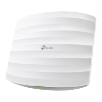
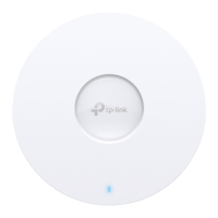
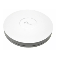
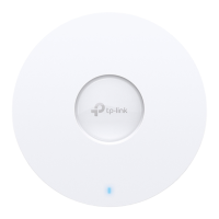
Details about the physical front panel of the EAP device.
Explanation of the LED indicator states and meanings.
Overview of rear panel components and ports including RESET button.
Step-by-step guide for securely mounting the EAP to a ceiling tile.
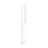
Step-by-step guide for securely mounting the EAP to a wall.
How to power the EAP using a compatible PoE switch (802.3at).
How to power the EAP using the provided power adapter.
Configure individual EAPs via Omada App or web browser for small networks.
Centralized management of EAPs using Omada Software, Hardware, or Cloud Controller.
This document describes a Wireless Access Point (EAP), specifically using the EAP660 HD as an example, though the instructions apply to other models like EAP610 and EAP620 HD. The device is designed for robust wireless connectivity in various network environments, offering both standalone and centralized management options.
The EAP functions as a Wireless Access Point, extending a local area network (LAN) wirelessly. It allows client devices to connect to the network via Wi-Fi. The device can be powered either through Power over Ethernet (PoE) from a compatible switch (802.3at standard) or via a dedicated power adapter. This flexibility in power supply makes it adaptable to different installation scenarios.
The EAP supports two primary configuration modes:
The EAP offers several features to enhance usability and network management:
http://tplinkeap.net. This interface allows for setting up a new username and password, modifying wireless parameters, and other advanced functions.https://omada.tplinkcloud.com) enables remote access to the Omada Software Controller and Omada Cloud-Based Controller. Users can log in with their TP-Link ID to manage controllers bound to their account, facilitating network administration from anywhere with internet access.The EAP includes features designed for easy maintenance and troubleshooting:
https://community.tp-link.com), a support website (https://www.tp-link.com/support), and setup videos (https://www.tp-link.com/support/setup-video/) to assist users with questions, technical support, and product guides.| Wireless Standards | IEEE 802.11a/b/g/n/ac/ax |
|---|---|
| Frequency | 2.4 GHz, 5 GHz |
| Antenna Type | Internal |
| Ethernet Ports | 1-2 Gigabit Ethernet ports |
| Power Supply | 802.3af/at PoE or External Power Adapter (depending on the specific model) |
| Dimensions | Varies by model |
| Mounting | Ceiling, Wall (depending on the specific model) |
| Wireless Speeds | Varies by model |
| Wireless Functions | Airtime Fairness, Band Steering |
| Wireless Security | WPA3 (depending on the specific model), MAC Address Filtering |
| Management | Omada Controller |
| Weight | Varies by model |
| Model | EAP225, EAP245, EAP265 HD, EAP660 HD, etc. |
| MIMO | 2x2, 3x3, 4x4 |