13Connection
3.4 Power On
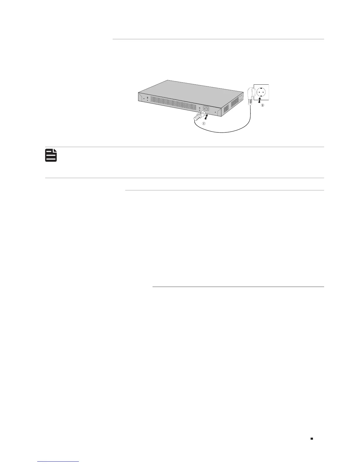
Plug in the negative connector of the provided power cord into the power socket of the device, and
the positive connector into a power outlet as the following figure shows.
Figure 3-3 Connecting to Power Supply
100-240V~50/60Hz 0.5A
Note:
The figure is to illustrate the application and principle. The power plug you get from the
package and the socket in your situation will comply with the regulation in your country, so they
may dier from the gure above.
3.5 Initialization
After the device is powered on, it begins the Power-On Self-Test. A series of tests run automatically
to ensure the device functions properly. During this time, its LED indicators will respond in the
following order:
1. The PWR LED indicator lights on all the time. The SYS LED and the LED indicators of all the ports
keep off.
2. After about one minute, the SYS LED and LED indicators of all the ports will flash momentarily and
then turn off.
3. Several seconds later, the SYS LED indicator will flash, which represents a successful initialization.
3.6 Accessing the Switch
After the initializaiton finished, you can access and manage the switch using the GUI (Graphical User
Interface) or using the CLI (Command Line Interface).
■
To access the switch using the GUI, open a web browser and type the default management address
http://192.168.0.1 in the address field, then press the Enter key. The default Username and Password
are both admin in lower case letters.
■
To access the switch using the CLI, you can use Telnet and SSH connection.
For the detailed configurations, please refer to the Configuration Guide and CLI Reference Guide.
The two guides can both be found on the resource CD or on the download center of our official
website: http://www.tp-link.com/en/download-center.html.
 Loading...