Do you have a question about the TP-Link TL-SG3452XP and is the answer not in the manual?
Details TP-Link JetStream L2/L2+ Managed Switch features for workgroups and departments.
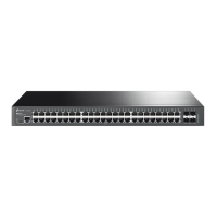
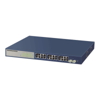
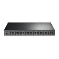
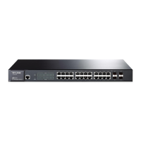
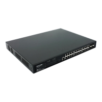
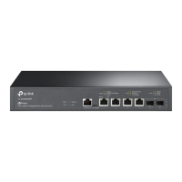
Shows front panel layouts for various TP-Link JetStream switch models.
Lists essential items included in the switch package for installation.
Outlines critical safety rules for device installation to prevent damage and injury.
Lists necessary tools for installing the switch, noting they are not included.
Provides instructions for desktop and rack mounting the managed switch.
Explains how to connect the switch's Ethernet port to a computer using an RJ45 cable.
Demonstrates the connection of an SFP/SFP+ module to the switch's SFP/SFP+ slot.
Describes connecting PCs or terminals via console cable for switch management through CLI.
Lists items to check after completing the switch installation for proper setup.
Guides on plugging in the power cord and connecting to the power outlet.
Explains the Power-On Self-Test (POST) process and LED indicator behavior during startup.
Introduces the two configuration options: Standalone and Controller modes.
Details how to configure and manage the switch individually using GUI or CLI.
Explains central management of multiple devices via Omada Hardware or Software Controller.
| Switching Capacity | 176 Gbps |
|---|---|
| Forwarding Rate | 130.95 Mpps |
| MAC Address Table | 32K |
| Jumbo Frame | 9 KB |
| Certifications | CE, FCC, RoHS |
| Ports | 4 x 10G SFP+ Slots |
| Standards and Protocols | IEEE 802.3, IEEE 802.3u, IEEE 802.3ab, IEEE 802.3x |
| Power over Ethernet (PoE) | Yes, IEEE 802.3af/at compliant |
| Mounting | Rack Mountable |
| Operating Temperature | 0°C to 40°C (32°F to 104°F) |
| Power Supply | 100-240V AC, 50/60Hz |
| Storage Temperature | -40°C to 70°C (-40°F to 158°F) |
| Operating Humidity | 10% to 90% (non-condensing) |
| Storage Humidity | 5% to 90% (non-condensing) |
| Dimensions | 17.3 × 13.0 × 1.7 in (440 × 330 × 44 mm) |