BLUE M
Blue M - - DC 146 Series Industrial Ovens, Models DC, DCW, DCI, DCC
Page 56
12.0 OVERTEMPERATURE PROTECTION
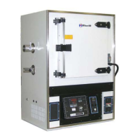
A Yokogawa 150L Limit Controller (OTP) is normally used for
overtemperature protection. This is a 1/16 DIN type controller, which is
mounted on the main control panel. A Type J thermocouple is used for
temperature sensing, which is placed in the workspace area. The high
limit is normally set approximately 11° C (20° F) higher than the oven
temperature setpoint.
Note: Alternate Limit Controllers may be used. Their overtemperature
protection operation will be very similar.
Setting the High Limit Setpoint:
1. Press the SET/ENT key for at least 3 seconds. SP will appear in the
top display. Press the Up / Down arrow keys to change the SP value
in the bottom display. Press the SET/ENT key to register this value.
2. Press the SET/ENT key for at least 3 seconds to return to the normal operating state.
High Limit Operation:
During normal operating conditions, Control Output contacts are closed to enable the heat contactor. When
the process temperature value exceeds the High Limit setpoint SP, the controller’s EXCEEDED and OUT
LEDs will illuminate. Control Output will open to remove power to the heat contactor. The EXCEEDED LED
will go out once conditions return to normal. The OUT LED will remain lit until the UT150L is reset.
Reset Operation:
When conditions return to normal and the EXCEEDED lamp extinguishes, press and hold the RESET key on
the controller for at least 2 seconds or until the OUT LED extinguish.
Note: The UT150L is configured for automatic reset during a power up condition only. This includes the
return of power after a power failure.
Controller Parameter Setup:
The pre-programmed controller configuration for your oven is documented in the Controller Parameter Setup
Chart, which is part of your Test Report. This is located in the Supplemental Instructions Section.
Important! The configuration set-up is mainly provided for your reference. Not all of the
parameters shown apply to your chamber. Changes to some of the set-up parameters may
drastically affect your chamber performance and void your warranty. Contact the TPS Service
Dept. before attempting any changes.
YOKOGAWA UT150L
 Loading...