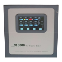
TQ Environmental Limited
Page 2 of 43 17654PM Issue: 3 December 2022
Table of Contents
PROPRIETARY .................................................................................................................................................... 4
COPYRIGHT ........................................................................................................................................................ 4
WARNINGS, CAUTIONS AND NOTES ............................................................................................................... 4
SAFETY WARNINGS .......................................................................................................................................... 5
1.0 Introduction ....................................................................................................................................................... 6
1.1 Specification ............................................................................................................................................. 7
2.0 Description ......................................................................................................................................................... 8
2.1 Adaptor PCB .................................................................................................................................................. 9
2.2 Control Board ................................................................................................................................................. 9
2.3 Display ............................................................................................................................................................ 9
2.4 Relay Board (Local) ....................................................................................................................................... 9
2.5 Remote Relay Board (if fitted) ...................................................................................................................... 10
2.6 Power Supply ............................................................................................................................................... 10
3.0 Operation ................................................................................................................................................... 12
3.1 Normal Operation ................................................................................................................................... 12
3.2 Gas/Input Alarms ................................................................................................................................... 13
3.3 Fault ....................................................................................................................................................... 16
3.4 Over Range Fault ................................................................................................................................... 16
3.5 Acknowledge Alarms ............................................................................................................................. 17
3.6 Reset Alarms ......................................................................................................................................... 17
3.7 Sensor View ........................................................................................................................................... 18
3.8 Disable Channel ..................................................................................................................................... 18
3.9 Inhibit Channel ....................................................................................................................................... 18
3.10 Data Log View ........................................................................................................................................ 19
4.0 System Menus ................................................................................................................................................. 20
4.1 Password Entry ............................................................................................................................................ 20
4.2 System Configuration ................................................................................................................................... 21
4.2 Channel Configuration ................................................................................................................................. 22
4.3 Alarm Configuration ..................................................................................................................................... 24
4.4 Relays Configuration .................................................................................................................................... 25
4.5 Calibration .................................................................................................................................................... 26
4.5.1 Zero Setup ............................................................................................................................................. 26
4.5.2 Span Setup ............................................................................................................................................ 27
4.6 Date/Time ..................................................................................................................................................... 27
4.7 Comms Configuration .................................................................................................................................. 27
4.8 Relay Test .................................................................................................................................................... 29
4.9 Default Data ................................................................................................................................................. 30
5.0 Modbus Communications ................................................................................................................................ 31
5.1 Communications .......................................................................................................................................... 31
5.1.1 Communication Specification ................................................................................................................ 31
5.2 Modbus Addresses ...................................................................................................................................... 31
5.2.1 Alarm State ............................................................................................................................................ 31
5.2.2 Gas Concentrations ............................................................................................................................... 34
6.0 Installation ....................................................................................................................................................... 35
6.1 Mechanical ................................................................................................................................................... 35
6.2 Electrical ....................................................................................................................................................... 35
6.2.1 Mains Supply ......................................................................................................................................... 35
6.2.2 Sensor Inputs ........................................................................................................................................ 35
6.2.3 Relay Outputs ........................................................................................................................................ 36
7.0 Commissioning ................................................................................................................................................. 37
7.1 Pre-Checks ................................................................................................................................................... 37
7.2 Input Card and Link Setup ........................................................................................................................... 37
7.2.1 4-20mA Input Sensors ........................................................................................................................... 37
7.2.2 Pellistor / Catalytic Input Sensors .......................................................................................................... 37
7.3 Power Up ...................................................................................................................................................... 38

 Loading...