INSTALLATION INSTRUCTIONS
The welding equipment is equipped with power voltage compensation. When power voltage moves
between ±15% of rated voltage, it will still work normally. When using a long cable, in order to
minimize the loss of voltage a bigger section cable is suggested. If the cable is too long it will affect
the performance of arcing and other system function, so stated length is recommended.
1. Make sure the fan intake of the machine is not covered or blocked to prevent the malfunction of
the cooling system.
2. Use earth cable that the section is no less than 6mm
2
to connect the housing and earth, the
method is from the connection in the back of the machine to the earth set, or make sure the earth
end of power switch reaches the earth. Both ways can be used for better security.
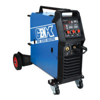
MIG 250SA Installation:
1. Connect the gas bottle with the flow meter and a gas hose to the back of the machine with the
chain.
2. Insert the jack plug of the earth cable into the dinse socket in the front panel and the clamp on to
the work piece.
3. Fit the MIG wire on to the spool adaptor and ensure correct wire direction.
4. Wire roll should turn clockwise rotation to let wire out.
5. Choose drive roll according to wire size.
6. Loosen the pressure wheel, fit wire through the spring inlet guide over drive roll and through the
brass outlet guide, close pressure wheel and adjust pressure so wire doesn’t slip but can slip if
wire gets jammed.
7. Fit the wire into the torch by hand and tighten the torch on to the euro output socket.
OPERATION INSTRUCTION
1. Open the valve of the gas cylinder and adjust the flow rate to 10 – 15 LPM Liters per Minute.
2. Use correct contact tip based on wire diameter.
3. Adjust the voltage and wire speed (amperage) knob to the correct settings based on the
thickness of the work piece and wire diameter.
4. Feed wire to end of torch tip with a stick out of about 8mm.
5. Press the torch trigger to feed out the wire and gas and begin to work.