Water Piping Connections
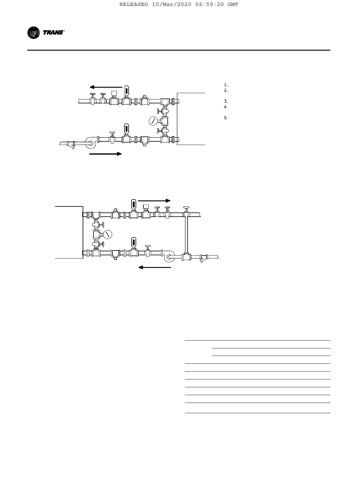
Figure 9. Typical evaporator water piping circuit
Valve
Thermometer (if field supplied)
Gate (Isolation) Valveor Ball
Flanged Connection 1/2” (13 mm
NPT Couplings
Drin, Vent, Anode
tes:
1.
water circuit.
2.
Flow switch 5S1 (Itemin Legend of Components) maybe installed in either the entering or leaving leg of the chilled
allows the operator to read either entering or leaving water pressure.
It is recommended to pipe the gauge between entering and leaving pipes. A shutoff valve on each side of the gauge
44
445
53
3
2
12
2
2
Inlet
Outlet
Figure 10. Typical condenser water piping circuits
2.
3.
Gate (Isolation) Valve or Ball Valv
4.
Thermometer (if field supplied)
5.
Flanged Connection 1/2” (13 mm)
NPT Couplings
6.
7.
Strainer
Drain, Vent, Anode
8.
Condenser Water Flow Switch (5S1
9.
3-Way Valve (Optional)
10.
Condenser Water Pump
Notes:
1.
Pressure Gauge
2.
water circuit.
3.
The Flow Switch 5S2 (Item 7 in Legend of Components) may be installed in either the entering or leaving leg of the chilled
It is recommended to pipe a single gauge between entering and leaving pipes.
4.
Some type of field-supplied temperature control device may be required to regulate the temperature of the heat-recovery
condenser water circuit. For application recommendations, see Trane Application Manual, “AM-FND-8”, titled “Heat-
Recovery Engineering Seminar”.
Install a bypass valve system to avoid circulating water through the auxiliary shell when the unit is shut down.
On multiple pass condensers, entering condenser water must enter at the lowest nozzle.
1
2
3
54
6
78
9
2
34
445
2
2
10
Outlet
Inlet
All standard units use grooved-pipe connections. These
are cut-groove end NSP (Victaulic™ style) pipe connec-
tion. Flanged connections for 300 PSI waterboxes use
welded flanges.
Piping joined using grooved type couplings, like all types
of piping systems, requires proper support to carry the
weight of pipes and equipment. The support methods
used must eliminate undue stresses on joints, piping
and other components; allow movement where required,
and provide for any other special requirements (i.e.,
drainage, etc.).
Note: Plug-type sensor extension cables are available
for purchase from Trane Parts Service if needed.
These sensor extension cables may be necessary
if the waterboxes are changed or if the tempera-
ture sensors are moved out into the unit piping
for better mixed temperature readings.
Table 2. Evaporator water piping connection sizes
EVSZ
ominal Pipe Size
1 Pass 2 Pass 3 Pass
Inch mm Inch mm Inch mm
050 10 273.0 8 219.1 6 168.3
080 12 323.9 10 273.0 8 219.1
142 16 406.4 12 323.9 10 273.0
210 16 406.4 14 355.6 12 323.9
250 16 406.4 14 355.6 12 323.9
Note:
EVSZ = Evaporator Shell Size; S = Short Shell, L = Long
Shell, E = Extended Shell
22 TCVHE-SVX04D-EN
Installation Water Piping
RELEASED 10/Mar/2020 06:59:20 GMT