Communication Interfaces
There are four connections on the UC800 that support
the communication interfaces listed. Refer to Figure 17, p.
33 for the locations of each of these ports.
• BACnet MS/TP
• Modbus Slave
• LonTalk® using LCI-C (from the IPC3 bus)
• Comm 4 using TCI (from the IPC3 bus)
Rotary Switches
There are three rotary switches on the front of the UC800
controller. Use these switches to define a three-digit ad-
dress when the UC800 is installed in a BACnet or Mod-
bus system (e.g., 107, 127, etc.). Valid addresses are 001
to 127 for BACnet and 001 to 247 for Modbus.
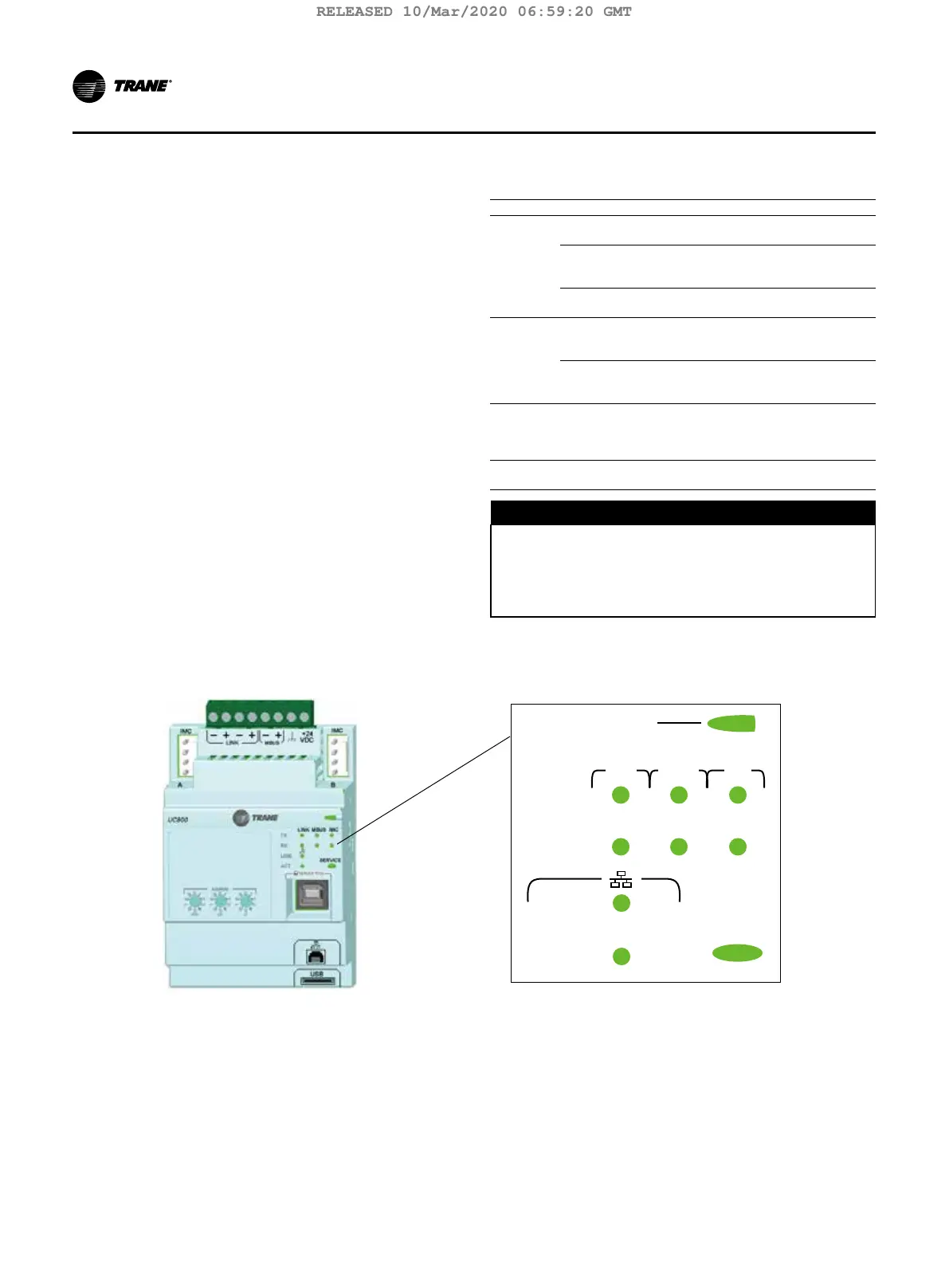
LED Description and Operation
There are 10 LEDs on the front of the UC800. Figure 18
shows the locations of each LED and Table 8, p. 34
describes their behavior in specific instances.
Figure 18. LED locations
LINK
IMCLINK MBUS
TX
RX
ACT
SERVICE
Marquee LED
Table 8. LED behavior
LED UC800 Status
Marquee
LED
Powered. If the Marquee LED is green solid, the
UC800 is powered and no problems exist.
Low power or malfunction. If the Marquee LED
is red solid, the UC800 is powered, but there are
problems present.
Alarm. The Marquee LED blinks Red when an alarm
exists.
LINK,
MBUS,
IMC
The TX LED blinks green at the data transfer rate
when the UC800 transfers data to other devices on
the link.
The Rx LED blinks yellow at the data transfer rate
when the UC800 receives data from other devices
on the link.
Ethernet
Link
The LINK LED is solid green if the Ethernet link is
connected and communicating. The ACT LED blinks
yellow at the data transfer rate when data ow is
active on the link.
Service
The Service LED is solid green when pressed. For
qualied service technicians only. Do not use.
D
NOTICE
Electrical Noise!
Maintain at least 6 inches between low-voltage (<30V)
and high voltage circuits. Failure to do so could result
in electrical noise that could distort the signals car-
ried by the low-voltage wiring, including IPC.
34 TCVHE-SVX04D-EN
Installation Controls
RELEASED 10/Mar/2020 06:59:20 GMT