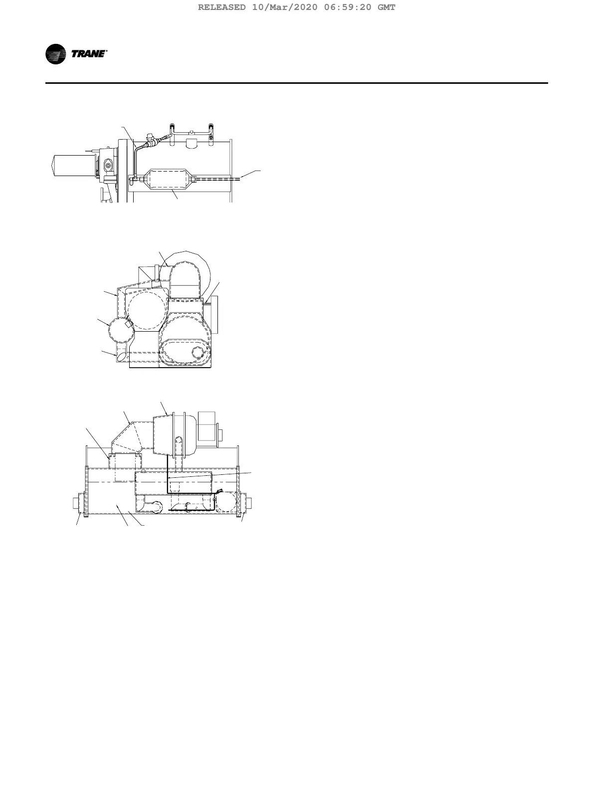
Figure 16. Recommended area for unit insulation
eductor
Filter drier and
eductor lines
Line
from
evap
Control
panel
support
Pipe (free
cooling only)
Pipe
Evaporator
Pipe
Suction
elbow
Suction
cover
Suction
connection
s
See Note 1
See Notes
Eductor lin
Notes:
1. Bulbwells, drain and vent connections must be accessible after insu-
lating.
2. Evaporators with ASME nameplates must have insulation cut out
around the nameplate. Do not glue insulation to the nameplate.
3. All units with evaporator marine waterboxes wrap waterbox shell
insulation with strapping and secure strapping with seal.
4. Apply two inch wide black tape on overlap joints. Where possible
apply three inch wide strip of 0.38 thick insulation over butt joint
seams.
5. Insulate all economizer supports.
32 TCVHE-SVX04D-EN
Insulation
RELEASED 10/Mar/2020 06:59:20 GMT