Electrical Notes:
1. EACH unit should be installed with its own dedicated power supply source. The power source
needs to be sized correctly for the unit capacity.
2. The rated voltage of the unit is as shown in this manual.
3. Before turning on, verify that the voltage is within the 187~252 V range (for 208/230 V, single
phase units).
4. Always use a grounded terminal and install a separate receptacle to supply power to the
air conditioner. For high voltage connections, flexible electrical conduit is recommended
whenever vibration transmission may create a noise problem within the structure.
5. Use a dedicated breaker and receptacle matched to the capacity of the air conditioner.
WARNING
1. Before obtaining access to terminals, all supply circuits must be disconnected.
2. Improperly installed and grounded field wiring poses fire and electrocution hazards. For
high voltage connections, flexible electrical conduit is recommended whenever vibration
transmission may create a noise problem within the structure. To avoid these hazards, you
MUST follow requirements for field wiring installation and grounding as described in the
National Electrical Codes (NEC) and your local/state electrical codes. All field wiring MUST
be performed by qualified personnel. Failure to follow these requirements could result in
death or serious injury.
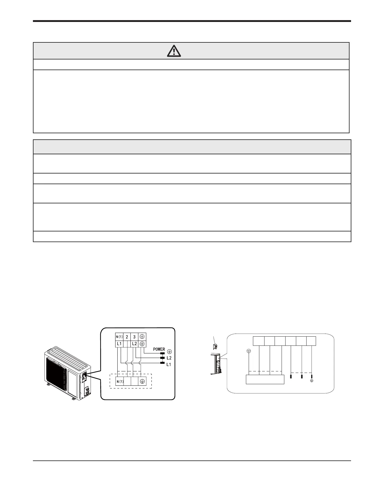
1. Remove the wire clip and connect the power connection wire and signal control wire terminals
according to the color coding.
2. Attach the wires to the terminals and make sure they are securely fastened. Refer to wiring
diagrams in this manual. An example is provided in the figures below:
Outdoor Wiring Connections
Wiring Precautions
NOTE: The wiring diagrams in this guide are included as a reference. The manufacturer has a policy
of continuous product and product data improvement and reserves the right to change design and
specications without notice. Always check the unit nameplate and wiring diagram for the actual unit
requirements.
3
2
Indoor unit connection
Handle
Indoor unit connection
2 3 L1
L1 L2
L2 GN(1)
POWER
(blue)
white
(blue)
white
black
red
(brown)
(brown)
black
(yellow-
green
green)
(yellow-
green
green)
9K-12K 18K-24K
G N(1) 2 3
88-M4MHW23-1A-EN 25
Installer's Guide

 Loading...