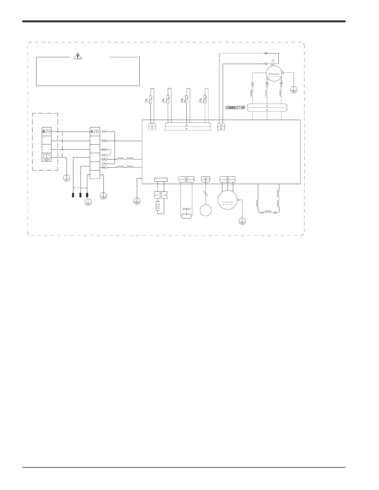
Outdoor Heat Pump Unit 24K
L
INDC1
WH
OG
INDC2
REACTOR
BOND HEATER
BOTTOM
RD RD
EH
HEAT
FAN MOTOR
VALVE
EXPANSION
ELECTRONIC
MANUAL
BK
RT4
OUTTUBE
TEMP.SENSOR 2
OVERLOAD PROTECTOR
4V
VT VT
4-WAY
4YV
VALVE
G
L5
L5
20K 15K 50K
XT
TERMINAL
BLOCK
BLOCK
TERMINAL
MAGNETIC
RING
G
L1
L1
2
3
BU
BN
BK
XT1
3
2
INDOOR UNIT
L1
L2
BN
BU
G
POWER
63633617
YEGN
L1
L2
G
AC_L
N
COM_INNER
RING
MAGNETIC
L3
L4
L4
M
G
RT1
X1
WARNING
EKV
FA
COMP
YEGN
SAT
WH
WH
OVC_COMP
OFAN
G
RDBU YE
G
W
V
U
RDYEBU
U(BU) V(YE) W(RD)
AP1
YEGN
RT3RT2
T_SENSOR
EXHAUST
TEMP. SENSOR
TEMP. SENSOR
OUTROOM
OUTTUBE
TEMP. SENSOR
MAGNETIC
RING
L2
COMP.
L2 L2
YEGN
G
PE
PRINTED CIRCUIT BOARD
WH BK
Please don't touch any terminal when the
voltage of terminal P(DC+) and N(DC-) at
AP1 is higher than 30V to prevent the
risk of electrical shock!
NOTE: The wiring diagrams in this guide are included as a reference. The manufacturer
has a policy of continuous product and product data improvement and reserves the
right to change design and specications without notice. Always check the unit
nameplate and wiring diagram for the actual unit requirements.
34 88-M4MHW23-1A-EN
Installer's Guide

 Loading...