48 MS-SVN056C-EN
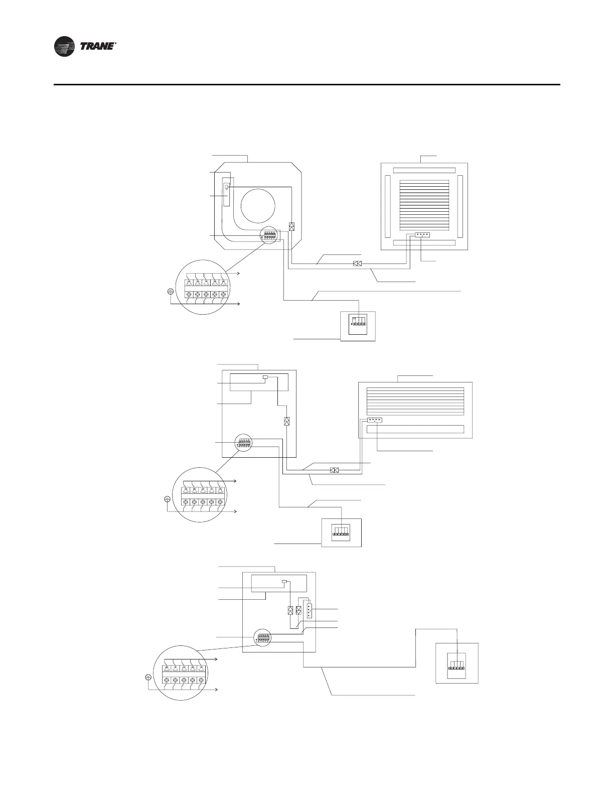
Wired Controller
1. Wiring diagram between wired controller and cassette indoor unit
2. Wiring diagram between wired controller and concealed indoor unit
3. Wiring diagram between wired controller and concealed high pressure indoor unit
ABCDE
ABCDE
Group of connecting 5-wire cables
Group of connecting
10-wire cables
Signal receptor
Cover of indoor unit
Shielded 5-wire cable
Connecting to wired control
Amplified view of terminal block
Indoor unit electric junction box
Electric box with 10 connecting poles
Main board
Terminal block
Ground
Terminal block
signal receptor
Front of indoor unit
Indoor unit electric junction box
Electric box with 10 connecting poles
Main board
Terminal block
signal receptor
Signal receptor
Group of connecting
10-wire cables
Group of connecting 5-wire cables
Shielded 5-wire cable
ABCDE
ABCDE
Connecting to wired control
Amplified view of terminal block
Terminal block
Ground
ABCDE
ABCDE
Connecting to wired control
Amplified view of terminal block
Terminal block
Ground
Shielded 5-wire cable
Group of connecting 10-wire cables
Group of connecting
5-wire cables
Terminal block signal receptor
Indoor unit electric junction box
Electric box with 10 connecting poles
Main board
Terminal block
signal receptor
ABCD
E
Back side of wired control
ABCD
E
Back side of wired control
ABCD
E
Back side of wired control