Do you have a question about the Trane 2TTX4018B and is the answer not in the manual?
Notes on using 2TTX4 & 2TTX5 units with specific indoor unit valve types.
Instructions for checking and reporting any damage found after uncrating the unit.
Guidance on determining and matching electrical power requirements to the unit's nameplate.
Instructions on removing tabs from the unit's basepan when removing it from the pallet.
Specifies setting the unit on a level support pad at least as large as the unit base pan.
Details minimum clearances from walls, shrubbery, and for service access.
Specifies that the top discharge area must be unrestricted for at least five feet above the unit.
Advises checking roof support and using isolation for units mounted on a roof.
States the maximum length for refrigerant lines from outdoor to indoor units.
Refers to other instructions for installing the indoor coil or air handler.
Explains how to check and change the orifice size for optimal system performance.
Informs that the unit ships with the correct orifice and a label.
Warns to use brazed joints, not soldered, for refrigerant lines.
Notes that condensing units have provisions for braze connections and pressure taps.
Covers determining line routing, considering bends, space, and insulation.
Advises on using isolation hangers and insulating lines to prevent noise transmission.
Details the operation and caution for the brass liquid line service valve.
Explains the operation of the brass gas line ball service valve.
Provides steps for preparing and brazing refrigerant lines.
Details pressurizing lines with nitrogen and using soap bubbles to find leaks.
Specifies pressurizing with dry nitrogen to 350-400 psi for leak checking.
Notes to keep refrigerant line valves closed and connect manifold gauges.
Describes evacuating the system to a micron gauge reading and checking for leaks.
Details charging refrigerant lines and indoor coil with vapor after evacuation.
Emphasizes exercising basic safety precautions to avoid electric shock during installation.
States power wiring and grounding must comply with local codes.
Recommends using color-coded low voltage wire and specifies max wire length.
Details setting the thermostat to OFF, applying power, and activating sump heat.
Directs users to page 8 for unit operational and checkout procedures.
Provides a chart of system faults, primary, and secondary causes.
Shows wiring for single/two-stage furnaces with air conditioners.
Illustrates wiring for variable speed air handlers with air conditioners.
Provides important notes regarding power supply, grounding, wire size, and ODT usage.
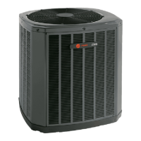
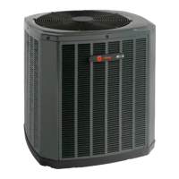
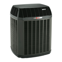
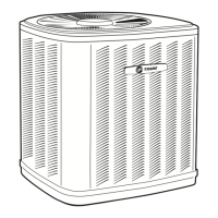
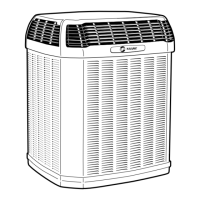
Shows the outline of the 2TTX4 & 2TTX5 units with key features labeled.
Provides a table of dimensions for various 2TTX4 and 2TTX5 models.
Details the mounting hole locations and dimensions for Base 3 configurations.
Details the mounting hole locations and dimensions for Base 4 configurations.
Lists items to check after installation, before system operation.
Details checking component operation in different modes (Cool, Heat, Auto) and performance.
Instructs to inform the owner about operation and deliver the Use and Care Booklet.
| Model | 2TTX4018B |
|---|---|
| Type | Heat Pump |
| Cooling Capacity (BTU/h) | 18000 |
| Heating Capacity (BTU/h) | 18000 |
| SEER Rating | 16 |
| Refrigerant | R-410A |
| Voltage | 208/230 |
| Phase | 1 |
| Frequency | 60 Hz |
| Compressor Type | Scroll |