Do you have a question about the Trane 2TWZ9 and is the answer not in the manual?
Provides general instructions for 2TWZ9 Heat Pump Units, including notes on indoor units and unit care.
Details guidelines for selecting unit location and preparing the installation site, including elevation and clearance.
Covers the process of installing refrigerant lines, including brazing and insulation requirements.
Explains the operation of brass liquid line and gas line service valves, including warnings.
Details the process of evacuating refrigerant lines and the indoor coil using a vacuum pump.
Covers power wiring, grounding, disconnect switches, and low voltage wiring requirements.
Explains the demand defrost control, its sensors, and fault identification.
Outlines the procedure for starting the compressor, including initial power application.
Refers to final operational and checkout procedures found on page 8.
Briefly mentions the installation of electric heaters according to separate instructions.
Notes that models have factory-installed quick start components.
Mentions field installation of an outdoor thermostat and refers to separate data.
Discusses the Seacoast Shield and its impact on the outdoor coil and warranty.
This document describes the installation and maintenance of Trane 2TWZ9 Heat Pump Units, providing comprehensive instructions for installers to ensure proper setup, operation, and longevity of the system. The guide emphasizes compliance with national, state, and local codes, and highlights specific precautions for installations in areas prone to snow accumulation and prolonged freezing temperatures.
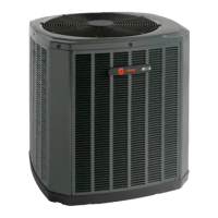
The Trane 2TWZ9 Heat Pump is designed to provide both heating and cooling for residential and commercial applications. It functions by transferring heat between the indoor and outdoor environments, offering an energy-efficient alternative to traditional heating and cooling systems. The unit is specifically designed to operate effectively in severe winter conditions, making it suitable for a wide range of climates. These outdoor units are intended for use with indoor units equipped with a Thermostatic Expansion Valve (TXV).
| Type | Heat Pump |
|---|---|
| Model | 2TWZ9 |
| Refrigerant | R-410A |
| Compressor Type | Variable Speed |
| Warranty | 10-Year Limited Warranty on Compressor |
| Stages | Variable |