EasyManua.ls Logo

Trane 2TWB0012-036AA User Manual

Trane 2TWB0012-036AA
8 pages
To Next Page IconTo Next Page
Page #1 background imageLoading...
Page #1 background image
ALL phases of this installation must comply with NATIONAL, STATE AND LOCAL CODES
IMPORTANT This Document is customer property and is to remain with this unit. Please return to service information
pack upon completion of work.
Installer’s Guide
space. The barrier should be constructed of materials
which will blend in with the building design.
3. Avoid locating the unit where condensation and freezing
of defrost vapor may annoy the customer. For instance,
installing the unit under a bedroom, kitchen, or picture
window may be annoying to the customer since conden-
sate and fog will occur during the defrost cycle.
4. Avoid locating the unit under the eaves or other over-
head structures as sizeable icicles may form and the unit
may be damaged by these falling icicles.
B. LOCATION AND PREPARATION
OF THE UNIT
1. When removing unit from the pallet, notice the tabs on
the basepan. Remove tabs by cutting with a sharp tool as
shown on page 2, Figure 2, and slide unit off of pallet.
2. The unit should be set on a level support pad at least as
large as the unit base pan, such as a concrete slab. If this
is not the application used please refer to application
bulletin SSC-APG002-EN.
3. The support pad must NOT be in direct contact with any
structure. Unit must be positioned a minimum of 12"
from any wall or surrounding shrubbery to insure
adequate airflow. Clearance must be provided in front of
Heat Pumps
2TWB0012-036AA
These instructions do not cover all variations in
systems nor provide for every possible contingency to
be met in connection with installation. All phases of
this installation must comply with NATIONAL, STATE
AND LOCAL CODES. Should further information be
desired or should particular problems arise which are not
covered sufficiently for the purchaser’s purposes, the matter
should be referred to your installing dealer or local distributor.
A. GENERAL
The following instructions cover 2TWB0012-036AA Heat
Pump Units.
NOTE:
These outdoor units may be used with indoor units
equipped with Thermostatic Expansion Valve or Accutron™
Flow Control Check Valve (F.C.C.V.) assembly for refrigerant
flow control only.
Check for transportation damage after unit is uncrated.
Report promptly, to the carrier, any damage found to the unit.
To determine the electrical power requirements of the unit,
refer to the nameplate of the unit. The electrical power
available must agree with that listed on the nameplate.
The Weathertron
®
Heat Pump has been designed and
manufactured to withstand and operate in severe winter
conditions. However, there are precautionary steps which
should be taken at the time of installation which will help
assure the efficient operation of the unit. It is recom-
mended that these precautions be taken for units
being installed in areas where snow accumulation and
prolonged below freezing temperatures occur.
1. Units should be elevated 3 to 12 inches above the pad or
rooftop, depending on local weather. This additional
height will allow better drainage of snow and ice (melted
during defrost cycle) prior to its refreezing. This should
prevent a build-up of ice around the unit which occurs
when unit is not elevated. Insure that drain holes in
unit base pan are not obstructed preventing
draining of defrost water.
2. If possible, avoid locations that are likely to accumulate
snow drifts. If not possible, a snow drift barrier should be
installed around the unit to prevent a build-up of snow
on the sides of the unit and should be of sufficient
distance from the unit to prevent restriction of airflow to
and from the unit. Also allow for proper maintenance
1
5 FT. ABOVE UNIT-UNRESTRICTED
18-BC52D5-5
Question and Answer IconNeed help?

Do you have a question about the Trane 2TWB0012-036AA and is the answer not in the manual?

Trane 2TWB0012-036AA Specifications

General IconGeneral
BrandTrane
Model2TWB0012-036AA
CategoryHeat Pump
LanguageEnglish

Summary

General Unit Information and Precautions

Outdoor Unit Installation Precautions

Measures for elevation, snow drifts, condensation, and eaves to ensure proper operation.

Unit Location and Preparation

Site Selection and Pad Requirements

Guidance on setting the unit on a level support pad and basepan tab removal.

Clearance and Airflow Requirements

Ensuring unrestricted airflow by maintaining proper clearances from walls and structures.

Accutron™™ Flow Control Valve

Accutron™™ Valve Orifice Sizing

Determining the correct orifice size for system rated performance.

Refrigerant Line Installation

Refrigerant Line Routing and Bending

Practical methods for running refrigerant lines, considering bends and space limitations.

Securing and Insulating Refrigerant Lines

Steps for fastening lines, insulation, and preventing contact between lines.

Service Valve Operation and Leak Checks

Brazing Refrigerant Lines

Procedures for brazing connections using nitrogen purge and proper techniques.

Refrigerant Line Leak Detection

Pressurizing lines with dry nitrogen and checking for leaks using soap bubbles.

System Evacuation and Charging

Evacuation Procedure Steps

Steps for evacuating refrigerant lines and indoor coil to specified micron levels.

Electrical Connections and Defrost Control

Electrical Wiring and Safety

Guidelines for power wiring, grounding, and safety precautions.

Defrost Control Operation and Faults

Understanding defrost control signals, fault identification, and pin identification.

Defrost Control Checkout

Procedures for checking normal operation and initiating a forced defrost.

Startup and Operational Procedures

Initial Compressor Start-Up Procedure

Procedure for setting thermostat and applying power to activate sump heat.

Unit Operational and Checkout Steps

Final unit operation and checkout procedures for proper performance.

Electric Heater Installation Notes

Instructions for installing electric heaters within the air handling device.

Outdoor Thermostat Installation

Guidance on field installation of an outdoor thermostat.

Seacoast Salt Shield Requirements

Information on applying salt shields for units near saltwater environments.

Checkout Procedure

Post-Installation System Checklist

Comprehensive list of checks for refrigerant lines, electrical, and system operation.
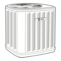
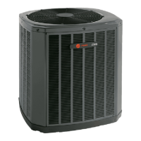
Related product manuals