18-BC52D5-5 5
Installer’s Guide
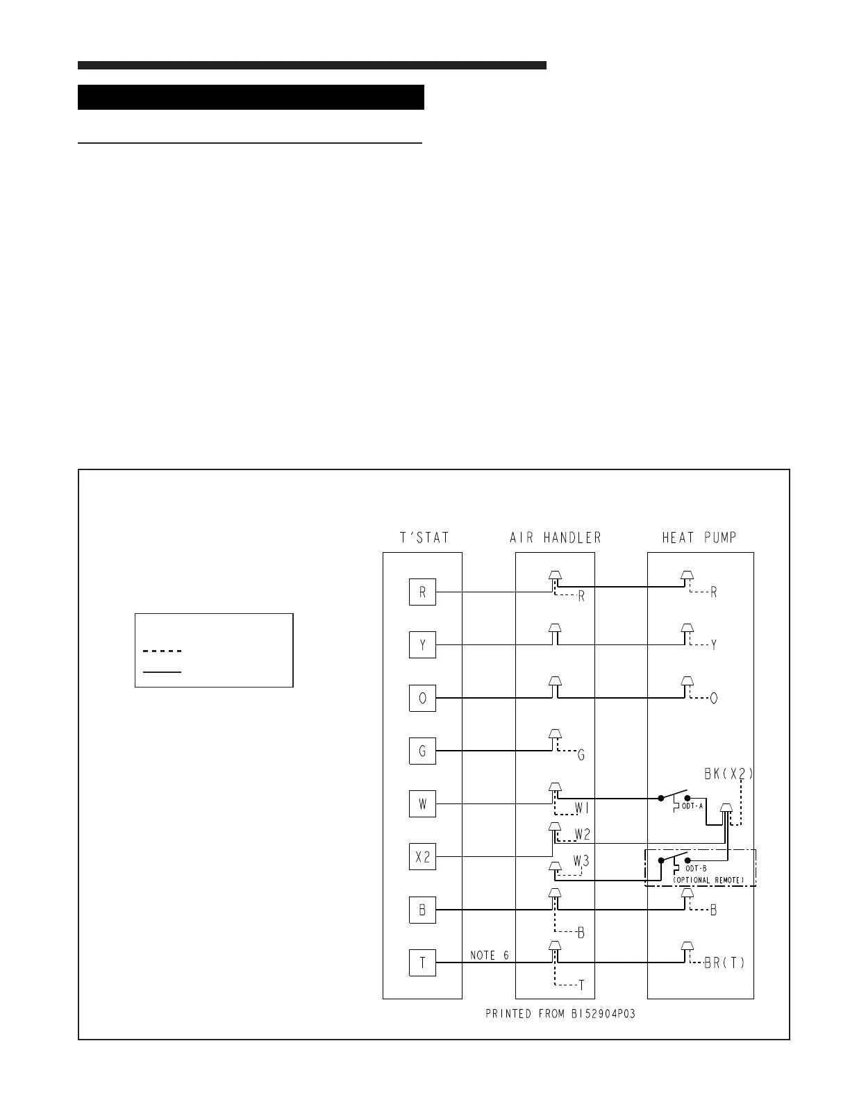
TYPICAL FIELD HOOK-UP DIAGRAM
LEGEND
FACTORY WIRING
FIELD WIRING
WARNING
!
Do NOT connect 24 VAC to T1 (ODS-A) terminal. ODS-A
thermistor WILL BE BLOWN.
H. COMPRESSOR START UP
After all electrical wiring is complete, SET THE THERMO-
STAT SYSTEM SWITCH IN THE OFF POSITION SO
COMPRESSOR WILL NOT RUN, and apply power by
closing the system main disconnect switch. This will activate
the compressor sump heat (where used). Do not change the
Thermostat System Switch until power has been applied for
one (1) hour. Following this procedure will prevent potential
compressor overload trip at the initial start-up.
I. OPERATIONAL AND CHECKOUT
PROCEDURES
Final phases of this installation are the unit Operational
and Checkout Procedures which are found in this instruction
on page 8. To obtain proper performance, all units must be
operated and charge adjustments made in accordance with
procedures found in the Service Facts.
J. ELECTRIC HEATERS
Electric heaters, if used, are to be installed in the air han-
dling device according to the instructions accompanying the
air handler and the heaters.
K. OUTDOOR THERMOSTAT
An outdoor thermostat TAYSTAT250B may be field installed.
For data, see wiring diagram attached to unit and instruction
sheet packaged with outdoor thermostat.
L. SEACOAST SALT SHIELD
If installed within one mile of salt water, including seacoasts
and inland waterways, models without factory supplied
Seacoast Salt Shields require the addition of BAYSEAC001
(Seacoast Kit) at installation time. Please refer to Applica-
tion Guide SS-APB006-EN: Trane - Seacoast Applications and
Seacoast Corrosion Protection Bulletin UN-SVB11A-EN.
Notes:
1. Be sure power supply agrees with equipment nameplate.
2. Power wiring and grounding of equipment must comply
with local codes.
3. Low Voltage wiring to be No. 18 AWG minimum conductor.
4. ODT-B Must be set lower than ODT-A.
5. If outdoor thermostats (ODT) are not used, connect WI to
W2 and W3.
6. N/A to programmable thermostat.
 Loading...