Home
Trane
Air Handlers
4TEE3C09A1000A
Page 14 (FIELD WIRING DIAGRAMS)
Trane 4TEE3C09A1000A - FIELD WIRING DIAGRAMS; Communicating & 24 VAC Cooling Wiring
20 pages
Manual
Save Page as PDF
To Next Page
To Next Page
To Previous Page
To Previous Page
Loading...
14
18-GE14D1-5
Installer’
s Guide
M
.
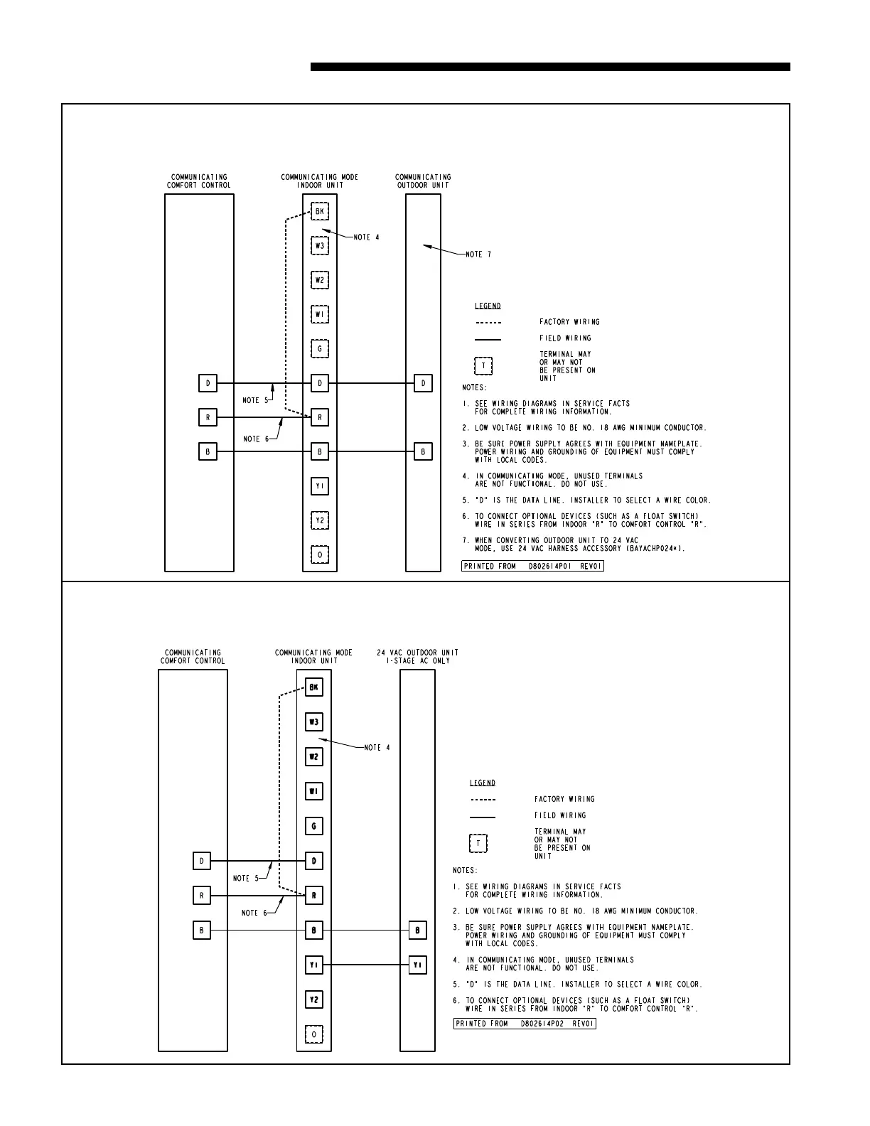
FIELD WIRING - REFERENCE ONLY
COMMUNICA
TING INDOOR UNIT
WITH COMMUNICA
TING COMFORT CONTROL
& COMMUNICA
TING OUTDOOR UNIT
COMMUNICA
TING INDOOR UNIT
WITH COMMUNICA
TING COMFORT CONTROL
& 24 V
AC SINGLE ST
AGE COOLING
13
15
Table of Contents
Main Page
Table of Contents
1
General Information
1
Installation Limitations & Recommendations
2
Two Piece Cabinet Disassembly
3
Unit Installation
4
Vertical Upflow
4
Horizontal Right
5
Duct Connections
6
Refrigerant Piping
6
Brazing to Evaporator Section
7
Condensate Drain Piping
7
Electrical - Power Wiring
8
Control Wiring
9
Airflow Adjustment
9
Unit Test Mode
10
User Interface Menus
11
Air Handler Flash Codes
13
Field Wiring
14
Electrical Connections to EAC
17
Outline Drawings
18
Checkout Procedures
20
Related product manuals
Trane 4TEE3C01A1000A
20 pages
Trane 4TEE3C04A1000A
20 pages
Trane 4TEE3C07A1000A
20 pages
Trane 4TEE3C49A1000A
8 pages
Trane 4TEE3C10A1000A
20 pages
Trane 4TEE3F39A1000A
18 pages
Trane 4TEE3F48A1000A
18 pages
Trane 4TEE3F31B1000B
16 pages
Trane 4TEE3F40B1000A
16 pages
Trane 4TEE3F49B1000A
16 pages
Trane 4TEE3F65B1000B
16 pages
Trane 4TEE3F48B1000A
18 pages