18-GE14D1-5 7
Installer’s Guide
F. BRAZING TO EVAPORATOR SECTION
NOTE: A brazing shield is provided in the Accessory
Kit accompanying this unit. This shield fits over the re-
frigerant fittings while brazing. Wet the shield before
brazing. See Figure 12.
IMPORTANT: Do NOT unseal refrigerant tubing until
ready to cut and fit refrigerant lines.
1. Remove both sealing caps from indoor coil.
2. Field supplied tubing should be cut squared-off, en-
suring the tube is still round and free of burrs at
the connecting end. Clean the tubing to prevent
contaminants from entering the system.
3. Run refrigerant tubing into the stub sockets of in-
door unit coil. Refrigerant line openings must be
completely sealed.
4.Braze and evacuate according to indoor and outdoor
installation instructions.
5.Seal around refrigerant lines.
NOTE: Painted areas of unit must be shielded during
brazing.
Figure 12. Braze Shield
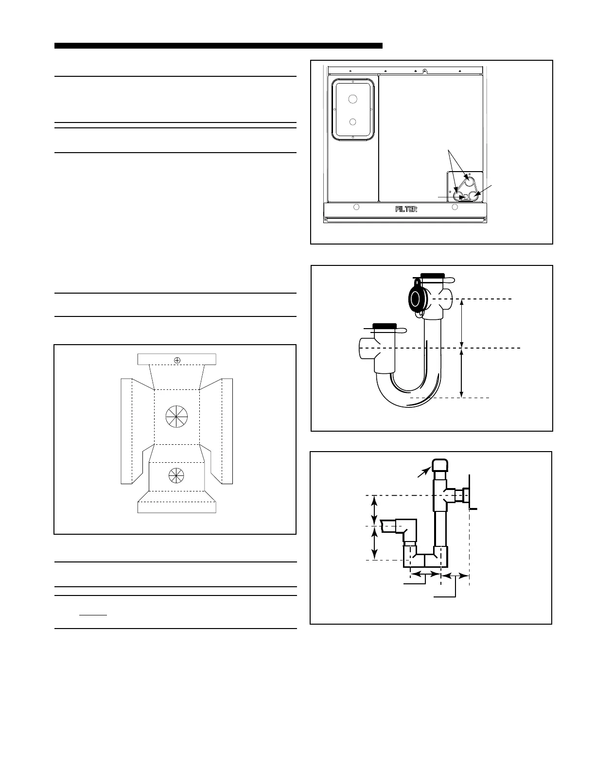
G. CONDENSATE DRAIN PIPING
NOTE: Make certain that the unit has been installed in a
level position to ensure proper draining.
NOTE: Use Teflon
®
tape on the Air Handler drain line connec-
tions!
Do Not Use pipe joint compound or PVC/CPVC
cement!
The indoor blower is downstream of the evaporator coil
which creates a negative pressure at the condensate
drain connections during operation. The condensate
drain connections in front of the indoor coil are 3/4"
NPT. The lower right connection is the primary drain.
See Figure 13.
Two secondary drain connections are provided for the
different orientations (See Figure 13). The lower of the
2" MIN.
2" MIN.
CAP OR PLUG
Trap must be within 4'
of air handler condensate
drain connection.
Close as possible
Figure 15. Field Fabricated Traps
2" MINIMUM
2" MINIMUM
EZT-105
Figure 14. Manufactured Traps
Figure 13. Drain Connections
3/4" NPT
Primary drain
connection
3/4" NPT
Secondary
drain
connection
Seal weep
hole