TEE3C49A-SF-1B 3
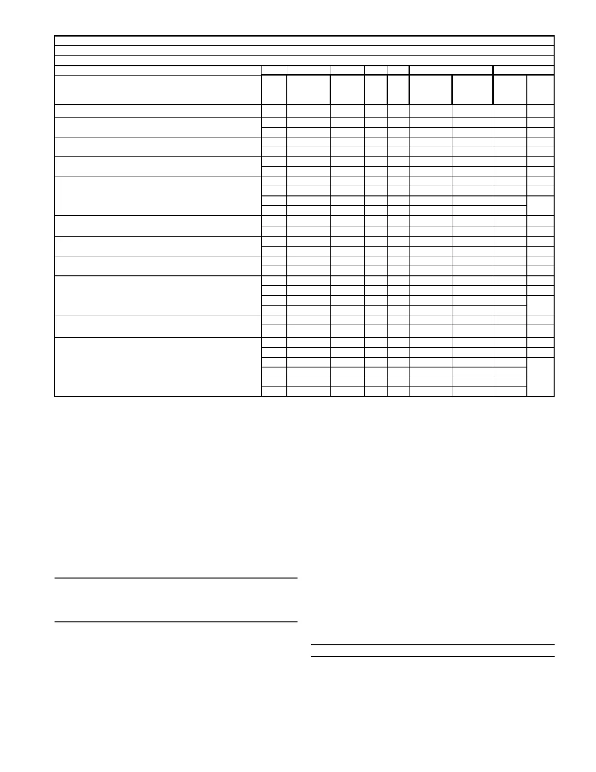
VOLT MTR AMPS
HEATER
AMPS MCA MOP
WITH OUT
HEAT
PUMP
WITH
HEAT
PUMP KW BTUH
CAPACITY
NOTES:
*** = 000, BRK or PDC - 000 = pigtails, BRK = contains circuit breakers & PDC = contains pull disconnect.
IMPORTANT: Any power supply and / or combination power supply, circuit or circuits must be wired and protected in accordance with local Electrical codes
MIN BLOWER SPEED
2/4TEE3C49
6.80 9 15
208 17.3 30 30 800 1100
3.60 12300
240 20.0 34 35 800 1100
4.80 16400
208 27.7 43 45 800 1100
5.76 19700
240 32.0 49 50 800 1100
7.68 26200
208 34.6 52 60 800 1400
7.20 24600
240 40.0 59 60 800 1400
9.60 32800
208 34.6 52 60 1100 1700
7.20 39300
240 40.0 59 60 1100 1700
9.60 52400
208 20.8 26 30
4.33
240 24.0 30 30 5.76
208 55.4 78 80 1100 1700 11.5 39300
240 64.0 89 90 1100 1700 15.4 52400
208 30.0 37 40 800 1400
7.20 24600
240 34.6 43 45 800 1400
9.60 32800
208 33.1 49 50 1100 1700
11.53 39300
240 38.2 55 60 1100 1700
15.36 52400
208 27.7 43 45 1400 1700
5.76 49200
240 32.0 49 50 1400 1700
7.68 65500
208 41.6 52 60
8.66
240 48.0 60 60 11.52
208 69.3 95 100 1400 1700 14.4 49200
240 80.0 109 110 1400 1700 19.2 65500
208 38.1 48 50 1400 1700
7.93 63900
240 44.0 55 60 1400 1700
10.56 85200
208 34.6 52 60
7.20
240 40.0 59 60 9.60
208 17.3 22 25 3.60
240 20.0 25 25 4.80
BAYHTR1419 BRKC
with single circuit power source kit BAYSPEK140B
circuit 1
circuit 2
circuit 3
BAYHTR3415-000C
BAYHTR1405***C
BAYHTR1408***C
BAYHTR1410***C
BAYHTR3410-000C
circuit 1
BAYHTR1419 BRKC
circuit 2
BAYHTR1415 BRKC
with single circuit power source kit BAYSPEK140B
circuit 1
BAYHTR1415 BRKC
circuit 2
TOTAL
HEATER
BAYHTR1425BRKC
UNIT TEST MODE
Unit Test Mode (Air Handler)
The system must be idle or thermostat switched to
“OFF” before the Unit Test will run the air handler. The
unit will work the same way in either the Communicating
Mode or 24 volt AC mode.
To access the Unit Test Mode scroll down through the
User Interface Information Menu until you see the Unit
Test option. Press ENTER. When prompted select YES
and press ENTER. When the User Interface displays
ARE YOU SURE? select YES and press ENTER to begin
the Unit Test.
NOTE: While in Test Mode all thermostat requests will
be ignored but if any button on the User Interface is
pressed, the Unit Test will exit. The Unit Test will exit
if a fault is detected during the test sequence.
The Unit Test will perform the following steps without
delays.
1. Start blower at 50% airflow and Energize EAC relay.
2. After 10 seconds, go to 100% airflow for 10 seconds.
(User Interface displays UNIT TEST – BLWR)
3. Energize Y1 relay for 15 seconds with 100% airflow.
(User Interface displays UNIT TEST – COOL)
4. De-energize Y1 relay and go to Electric Heat airflow.
(User Interface displays UNIT TEST – HEAT)
5. Energize blower interlock and stage 1 heat relay.
6. Energize humidifier relay.
7. After 1 second energize stage 2 heat relay.
8. After 1 more second energize stage 3 heat relay.
9. After 5 seconds de-energize blower interlock, stage
1, 2 & 3 heat, humidifier and EAC relays.
(User Interface displays UNIT TEST – EXIT)
Displayed for three seconds
NOTE: Airflow is default or programmed selections.