18-AC104D1-1G-EN 11
STEP 1 - Use the refrigerant line total length
and lift measurements from Section 5.3.
Total Line Length = __________ Ft.
Vertical Change (Lift) = __________ Ft.
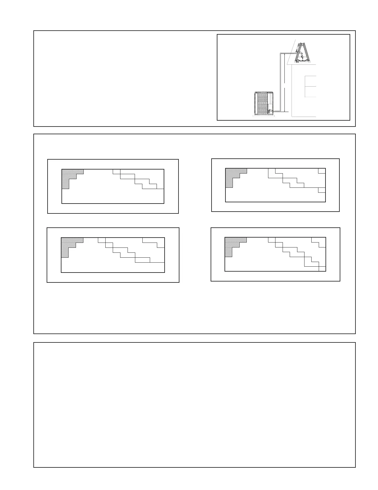
14.2 Subcooling Charging in Cooling (Above 55º F Outdoor Temp.)
LIFT
Design Subcooling Value = __________º F
(from nameplate)
Subcooling Correction = __________º F
Final Subcooling Value = __________º F
STEP 2 -
Determine the nal subcooling value using total Line Length and Lift measured in STEP 1 and the charts below.
024N Models
50
1°
40
30
25
Use Design Subcooling
15
10
0
20 30 40 50 60 70 80 90 100 110 120130 140 150
Add 1°
Add 1°
TOTAL REFRIGERANT LINE LENGTH (FT) - [ includes lift ]
SUBCOOL CHARGING CHART CORRECTIONS TABLE (FOR LINE LENGTH AND RISE)
Add 2°
REFRIGERANT LINE LIFT (FT)
048N Models
50
1°
40
1°
30
25
Use Design Subcooling
15
10
0
20 30 40 50 60 70 80 90 100 110 120130 140 150
REFRIGERANT LINE LIFT (FT)
SUBCOOL CHARGING CHART CORRECTIONS TABLE (FOR LINE LENGTH AND RISE)
Add 4°
TOTAL REFRIGERANT LINE LENGTH (FT) - [ includes lift ]
Add 2°
Add 1°
Add 1°
060N Models
50
1°
40
1°
30
25
Use Design Subcooling
15
10
0
1°
20 30 40 50 60 70 80 90 100110 120130 140 150
Add 4°
Add 2°
Add 1°
Add 1°
REFRIGERANT LINE LIFT (FT)
SUBCOOL CHARGING CHART CORRECTIONS TABLE (FOR LINE LENGTH AND RISE)
TOTAL REFRIGERANT LINE LENGTH (FT) - [ includes lift ]
036N Models
50
4°
40
30
25
Use Design Subcooling
15
1°
10
0
20 30 40 50 60 70 80 90 100 110 120130 140 150
Add 1°
Add 2°
REFRIGERANT LINE LIFT (FT)
SUBCOOL CHARGING CHART CORRECTIONS TABLE (FOR LINE LENGTH AND RISE)
TOTAL REFRIGERANT LINE LENGTH (FT) - [ includes lift ]
Add 1°
STEP 3 - Stabilize the system by operating for a minimum of 20 minutes.
At startup, or whenever charge is removed or added, the system must be operated for a minimum of 20 minutes to
stabilize before accurate measurements can be made.
STEP 4 - Measure the liquid line temperature and pressure at the outdoor unit’s service valve.
Measured Liquid Line Temp = __________ º F
Liquid Gage Pressure = __________ PSIG
Final Subcooling Value = __________ º F
STEP 5 - Use the final subcooling value, refrigerant temperature and pressure from STEP 4, to determine the
proper liquid gage pressure using Table 14.2.
Example: Assume a 12º F Final Subcooling value and liquid temp of 90º F.
1. Locate 12º F Final Subcooling in Table 14.2.
2. Locate the Liquid Temperarature (90º F) in the left column.
3. The Liquid Gage Pressure should be approximately 327 PSIG. (This is the shown as the intersection of the
Final Subcooling column and the Liquid Temperature row in Table 14.2.)

 Loading...