EasyManua.ls Logo

Trane 4TXCB004DS3HCC - User Manual

Trane 4TXCB004DS3HCC
10 pages
Print Icon
To Next Page IconTo Next Page
Loading...
Table of Contents
General .................................................................................1
Application Information ......................................................1
Recommendation ................................................................2
Furnace in Upflow Position ................................................2
Furnace in Downflow Position ...........................................2
Furnace in Horizontal Right Position.................................3
Furnace in Horizontal Left Position ...................................4
Maximum Airflow Setting (CFM) ........................................5
Installing / Brazing Refrigerant Lines ................................5
Leak Check ..........................................................................5
Condensate Drain Piping ....................................................5
Cleaning the Coil .................................................................6
Outline Drawing ...................................................................7
Troubleshooting Indoor TXV / Cooling Mode ....................8
Installer’s Guide
ALL phases of this installation must comply with NATIONAL, STATE AND LOCAL CODES
IMPORTANT — This Document is customer property and is to remain with this unit. Please return to service information pack
upon completion of work.
IMPORTANT: Review your installation requirements. Check
the table on the outline drawing and note all dimensions for
your coil before beginning the installation.
Figure 1
18-AD42D1-1B-EN
Cased Aluminum "Convertible" Coil
Model:
4TXCB004DS3HCC
4TXCD010DS3HCC
NOTE:
OPTIONAL DOWNFLOW GASKET INSTALLATION: For
unusually humid applications that expect prolonged
operation above 70% RH, it is recommended to use the
BAYGSKT001A0 gasket kit to prevent water from forming
on the bottom of the drain pan and dripping into the
supply ductwork.
WARNING
!
This product can expose you to chemicals including
lead, which are known to the State of California to case
cancer and birth defects or other reproductive harm.
For more information go to www. P65Warnings.ca.gov
A. GENERAL
This coil is designed for use in combination with a heat pump or
cooling outdoor section using R-410A REFRIGERANT.
The 4TXC equipment has been evaluated in accordance with
the Code of Federal Regulations, Chapter XX, Part 3280 or
the equivalent. “Suitable for Mobile Home use” The height of
the Furnace, Coil and discharge duct work must be 7 ft. or less.
Inspect the coil for shipping damage. Notify the transportation
company immediately if the coil is damaged.
B. APPLICATION INFORMATION
1. FURNACE AND COIL
The coil MUST BE installed downstream (in the outlet air)
of the furnace.
2. INDOOR UNIT AIRFLOW
Indoor unit must provide the required airflow for the heat
pump or cooling combinations approved for this coil.
WARNING (Medium/high pressure)
Contains Refrigerant!
System contains oil and refrigerant under high pressure.
Recover refrigerant to relieve pressure before opening the
system. See unit nameplate for refrigerant type. Do not
use non-approved refrigerants, refrigerant substitutes, or
refrigerant additives.
Failure to follow proper procedures or the use of non-
approved refrigerants, substitutes, or refrigerant additives
could result in death, serious injury, or equipment damage.
WARNING
!
Question and Answer IconNeed help?

Do you have a question about the Trane 4TXCB004DS3HCC and is the answer not in the manual?

Summary

A. GENERAL

B. APPLICATION INFORMATION

Details on applying the coil with furnaces and indoor unit airflow requirements.

C. RECOMMENDATION

D. FURNACE IN UPFLOW POSITION

1. UPFLOW COIL CONVERSION

Optional steps to remove coil components for maximum airflow efficiency.

2. UPFLOW GAS FURNACE

Steps for applying gasket material and securing the coil to the furnace.

E. FURNACE IN DOWNFLOW POSITION

1. DOWNFLOW COIL CONVERSION

Optional steps to remove coil components for maximum airflow efficiency.

2. DOWNFLOW GASKET INSTALLATION (OPTIONAL)

Instructions for applying an optional gasket kit for humid applications.

3. DOWNFLOW GAS FURNACE

Procedure for positioning and securing the coil case to the furnace.

F. FURNACE IN HORIZONTAL RIGHT POSITION

1. HORIZONTAL RIGHT COIL CONVERSION

Optional steps to remove coil components for maximum airflow efficiency.

2. Attach the coil and furnace...

Instructions for attaching the coil and furnace in the specified orientation.

3. There are self drilling screws...

Guidance on using self-drilling screws for connection and sealing gaps.

G. FURNACE IN HORIZONTAL LEFT POSITION

1. HORIZONTAL LEFT COIL CONVERSION

Optional steps to remove coil components for maximum airflow efficiency.

2. Splash Guard installation...

Steps for installing the splash guard to prevent water blowoff.

3. Attach the coil and furnace...

Instructions for attaching the coil and furnace in the specified orientation.

4. Insert standoffs into clearance...

Procedure for using standoffs and screws for alignment and sealing gaps.

H. MAXIMUM AIRFLOW SETTING (CFM)

I. INSTALLING;BRAZING REFRIGERANT LINES

1. The following steps are to be considered...

Steps for determining line routing, bends, and securing tubing.

PAINTED AREAS OF THE UNIT MUST BE SHIELDED DURING BRAZING.

Important safety note regarding shielding painted areas during brazing.

5. Use good brazing technique...

Guidance on brazing techniques, bends, insulation, and line contact.

When replacing the TXV bulb...

Instructions for correctly reinstalling the TXV bulb and insulation.

J. LEAK CHECK

1. Using a manifold gauge...

Procedure for connecting nitrogen and pressurizing lines for leak checking.

3. Leak check brazed line connections...

Method for checking leaks with soap bubbles and repairing them.

4. Evacuate and charge the system...

Instructions for evacuating and charging the system per outdoor unit guidelines.

K. CONDENSATE DRAIN PIPING

1. The drain hole in the drain pan...

Ensuring the drain hole in the drain pan is cleared of insulation.

2. Insulate the primary drain line...

Recommendation to insulate the primary drain line to prevent sweating.

3. Connect the secondary drain line...

Instructions for connecting the secondary drain line without a trap.

L. CLEANING THE COIL

The two piece door allows removal...

Instructions for removing panels and cleaning the coil with brush and vacuum.

The foil covered insulation should...

Guidance on wiping down insulation and vacuuming dust for air quality.

Overview

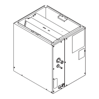
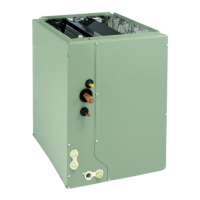
This document is an installer's guide for a cased aluminum "convertible" coil, specifically models 4TXCB004DS3HCC and 4TXCD010DS3HCC. It provides comprehensive instructions for the installation, operation, and maintenance of the coil, emphasizing compliance with national, state, and local codes.

Function Description:

The device is an indoor cased aluminum "convertible" coil designed for use in combination with a heat pump or cooling outdoor section that uses R-410A refrigerant. Its primary function is to facilitate heat exchange in an HVAC system, working in conjunction with a furnace to provide conditioned air. The "convertible" aspect suggests its adaptability to various installation orientations, including upflow, downflow, horizontal right, and horizontal left, to suit different residential configurations, including mobile homes, provided the total height of the furnace, coil, and discharge ductwork is 7 ft. or less.

Important Technical Specifications:

The guide provides a table of specifications for the two models:

  • 4TXCB004DS3HCC:
    • Shipping Weight: 58 lbs.
    • Refrigerant Control: TXV (Non-Bleed)
    • Height "A": 22-1/2 in.
    • Overall Width "B": 17-1/2 in.
    • Opening Width "C": 16-5/8 in.
    • Top Opening "D": 15-3/4 in.
    • Gas Connection: 7/8 in.
    • Liquid Connection: 3/8 in.
    • Matched Furnace Width (No Adapter Required): 17-1/2 in.
    • Drain Pan: Plastic
  • 4TXCD010DS3HCC:
    • Shipping Weight: 81 lbs.
    • Refrigerant Control: TXV (Non-Bleed)
    • Height "A": 30-3/4 in.
    • Overall Width "B": 24-1/2 in.
    • Opening Width "C": 23-5/8 in.
    • Top Opening "D": 22-3/4 in.
    • Gas Connection: 7/8 in.
    • Liquid Connection: 3/8 in.
    • Matched Furnace Width (No Adapter Required): 24-1/2 in.
    • Drain Pan: Plastic

Maximum Airflow Settings (CFM):

The guide specifies maximum airflow settings to prevent water blow-off in certain installation positions:

  • 4TXCB004DS3HCC:
    • Upflow: 1350 CFM
    • Downflow: 1100 CFM
    • Horizontal Left: 1200 CFM
    • Horizontal Right: 1350 CFM
  • 4TXCD010DS3HCC:
    • Upflow: 2250 CFM
    • Downflow: 1850 CFM
    • Horizontal Left: 2000 CFM
    • Horizontal Right: 2250 CFM

The TXV (Thermostatic Expansion Valve) setting on this unit may run high superheat (15-25°F) by design when measured at the outdoor unit.

Usage Features:

  • Installation Flexibility: The coil is designed for various orientations (upflow, downflow, horizontal right, horizontal left) to accommodate different furnace setups.
  • Downstream Installation: The coil MUST be installed downstream (in the outlet air) of the furnace.
  • Airflow Optimization: For certain orientations, optional removal of coil components (like outer water diverter baffles) is recommended to maximize airflow efficiency.
  • Splash Guard (Horizontal Left): A splash guard installation is required in horizontal left configurations to prevent water blowoff.
  • Refrigerant Lines: Detailed instructions are provided for installing and brazing refrigerant lines, emphasizing the use of good brazing techniques, minimizing sharp bends, and insulating the suction line. The TXV bulb must be protected during brazing.
  • Leak Check: A procedure for leak checking brazed line connections using dry nitrogen and soap bubbles is outlined.
  • Condensate Drain Piping: Connections are located in the drain pan. While a field-fabricated trap is not required for proper drainage due to positive furnace pressure, it is recommended to prevent efficiency loss. The primary drain line should be insulated to prevent sweating.
  • Optional Downflow Gasket Installation: For unusually humid applications (prolonged operation above 70% RH), a BAYGSKT001A0 gasket kit is recommended to prevent water from forming on the bottom of the drain pan and dripping into the supply ductwork.

Maintenance Features:

  • Coil Cleaning: The coil features a two-piece door design that allows for easy removal of outer casing doors without interfering with refrigerant or condensate lines. Once the outer doors are removed, the inner coil panels can be easily removed, allowing for the inside and outside of the coil to be cleaned with a brush and vacuum.
  • Insulation Cleaning: The foil-covered insulation should be wiped down, and residual dirt and dust vacuumed up to maintain good air quality.
  • Troubleshooting Guide: A detailed flowchart is provided for troubleshooting indoor TXV in cooling mode, covering issues related to sub-cooling, superheat, airflow, liquid line temperature, and indoor temperature. This guide helps diagnose problems such as low superheat, high superheat, and restricted outdoor coil, leading to solutions like correcting airflow, checking refrigerant charge, or replacing the TXV.
  • Pre-Maintenance Check: Before troubleshooting, it is important to ensure the blower wheel, indoor, and outdoor coils are clean.

Trane 4TXCB004DS3HCC Specifications

General IconGeneral
BrandTrane
Model4TXCB004DS3HCC
CategoryFurnace
LanguageEnglish

Related product manuals