Do you have a question about the Trane 8B1A026M2PSAB and is the answer not in the manual?
Guide for gas-fired furnaces with high efficiency motors.
General safety warning for qualified personnel handling equipment.
Warnings regarding fire/explosion risks and actions to take if gas is smelled.
Warnings about electrical hazards during servicing and potential fire/explosion.
Warnings about CO poisoning from improper venting and ensuring proper ventilation.
Warning about furnace placement on combustible flooring and subbase requirements.
Warning about chemical exposure, including lead, known to cause cancer and birth defects.
Propane gas heavier than air, risk of collection in low areas, odorant fade.
Warnings about bypassing door switches and touching IFC components.
Warning against manually lighting the furnace.
Importance of proper maintenance and ensuring blower door is secure.
Furnaces not approved for manufactured housing, trailers, or RVs.
Procedure for shutting off gas supply in case of failure.
Avoid storing flammable materials near the unit.
Do not use semi-rigid metallic gas connectors inside the furnace.
Warning about electrical components and moving fans during installation/servicing.
Do not install filter directly above furnace in horizontal applications.
Turn off power before servicing filters to avoid contact with moving parts.
Prohibits venting into unlined masonry or concrete chimneys.
Importance of inspecting chimney liner for cracks or leaks.
Disconnect switch must be locked open before servicing.
Shut off gas supply if overheating occurs or gas fails to shut off.
Do not connect furnace line voltage to a GFCI protected circuit.
Do not install furnace in corrosive or contaminated atmosphere.
Be careful of sharp edges on equipment during installation or servicing.
Use a backup wrench on the gas valve when installing gas piping.
Take precautions to prevent freeze-up of water pipes during furnace shutdown.
Maintain manifold pressure in high altitude installations.
Recommend overflow drain pan for installations over finished ceilings.
Do not touch the igniter; it is extremely hot.
Label wires before disconnection and verify proper operation.
Do not use furnace as a construction heater; avoid corrosive atmospheres.
Integrated furnace control is polarity sensitive.
UV light can deteriorate plastic blower housing; avoid third-party UV air cleaners.
Follow steps for appliances connected to venting system for safe operation.
Table listing accessory kits and their compatibility with furnace models.
Essential safety practices and precautions for furnace installation, servicing, and operation.
Guidelines on codes, regulations, and handling the furnace upon receipt.
Requirements for furnace placement, including clearances to combustible materials and service access.
List of common air contaminants that can cause safety and performance issues.
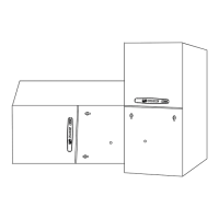
Dimensional drawings for the 14.5-inch width furnace cabinet.
Dimensional drawings for the 17.5-inch width furnace cabinet.
Dimensional drawings for the 21.0-inch width furnace cabinet.
Dimensional drawings for the 24.5-inch width furnace cabinet.
Instructions for removing the front panel of S8X2 and S8B1/S8X1 furnaces.
Guidelines for installing the furnace horizontally in attics or crawlspaces.
Diagrams for gas piping connections in upflow and downflow orientations.
Diagrams for gas piping connections in horizontal orientations.
Tables for gas pipe capacity and main burner orifice drill sizes.
Procedure and table for checking gas flow rate and input.
Steps for adjusting manifold pressure for 1st and 2nd stage gas heat.
Information on reducing input rate for high altitudes and orifice selection.
Table listing kit model numbers for high altitude adjustments.
Guidelines for venting fan-assisted combustion systems and types of chimneys.
Considerations for venting into masonry chimneys, including liner types.
Practices to minimize corrosion and recommendations for venting.
Minimum height requirements for vent termination based on roof pitch and wall placement.
Requirements for air supply for combustion and ventilation, unconfined spaces.
Requirements for combustion air in confined spaces, including outdoor air and openings.
Illustrations showing ventilation methods for confined spaces from outdoors or attic/crawlspace.
General guidelines for air duct system installation and flexible connections.
Specific rules for return ducting, including side and back returns.
Instructions for connecting supply ducts to upflow and horizontal furnaces with coils.
Instructions for connecting supply ducts to horizontal right and downflow furnaces with coils.
Instructions for connecting ducts to horizontal and downflow furnaces without coils.
Methods for connecting return ducts in upflow installations within a closet.
Methods for connecting return ducts using a ducted pedestal in upflow installations.
Connecting return ducts with side returns on a ducted pedestal.
Connecting return ducts for upflow furnaces with single or dual side returns.
Methods for connecting return ducts in downflow installations with top return.
Connecting return ducts in downflow installations with top return and filter box.
Information on filter size dependency and external installation.
Steps for preparing upflow installations for bottom and side return air filters.
Guidelines for installing return air filters externally in horizontal configurations.
Wiring diagrams for single-stage heating thermostats with S8B1/S8X1 furnaces.
Wiring diagrams for two-stage heating thermostats with S8X2 furnaces.
Diagrams for twinning S-Series furnaces with 2-stage heat/1-stage cool thermostats.
Diagrams for twinning S-Series furnaces with 2-stage heat/2-stage cool thermostats.
Twinning diagrams involving transformers and single-stage thermostats.
Ensure duct connections, filters, venting, and panels are properly secured before start-up.
How to initiate furnace operation and check flame control module function.
Inspect gas valve, purge lines, check for leaks with soapy solution.
Checking limit switch operation and blower airflow for overheating conditions.
Illustrations of approved venting options for upflow furnace applications.
Illustrations of approved venting options for horizontal left furnace applications.
Illustrations of approved venting options for horizontal right furnace applications.
Illustrations of approved venting options for downflow furnace applications.
Steps for converting inducer orientation for upflow top venting.
Steps for converting inducer orientation for upflow left side venting.
Steps for converting inducer orientation for upflow right side venting.
Steps for converting inducer orientation for horizontal left venting.
Steps for converting inducer orientation for horizontal left top venting.
Steps for converting inducer orientation for horizontal right top venting.
Steps for converting inducer orientation for downflow left side venting.
Steps for converting inducer orientation for downflow right side venting.
Steps for converting inducer orientation for downflow top venting.
Control system menu flow for single-stage S8B1/S8X1 outdoor units.
Control system menu flow for two-stage S8X1 outdoor units.
Control system menu flow for single-stage S8X2 outdoor units.
Control system menu flow for two-stage S8X2 outdoor units.
Explanation of display codes for system status and modes.
Table showing CFM vs. ESP for various taps and models.
Examples demonstrating airflow adjustment for cooling/HP and two-stage outdoor units.
List of menu options and their explanations.
Table of alarm error codes and their corresponding explanations.
Steps for viewing and clearing the last 6 faults, and resetting factory defaults.
Diagrams showing IFC component layout for S8X1 and S8X2 models.
Timing of EAC and HUM relays during furnace operation.
Detailed steps for 1st stage gas heating operation, including safety checks and ignition.
Steps for 2nd stage gas heating operation specific to S8X2 furnaces.
Steps for single stage cooling operation.
Steps for two stage cooling operation.
Steps for single stage heat pump operation.
Steps for two stage heat pump operation.