12
18-GF16D1-1A-EN
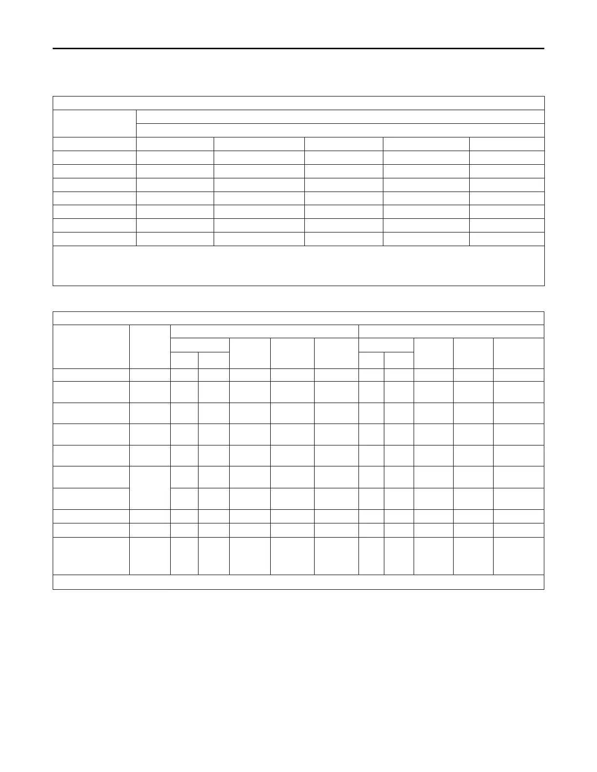
Table 5. Air Flow Performance
A4AH4E30A1B30A
EXTERNAL STATIC
(in w.g)
AIRFLOW
Speed Taps: 208 – 230 VOLTS
High Med-High
Med † Med-Low Low
0.1 1192 1126 1070 995 940
0.2 1148 1079 1021 943 885
0.3 1103 1031 971 890 828
0.4 1057 980 919 834 767
0.5 1009 929 865 775 702
0.6 961 875 810 714 635
0.7 911 820 753 651 564
1. Values are with wet coil, no filter, and no heaters
2. CFM Correction for dry coil = Add 3%
3. † = Factory Setting
4. Low = Tap 1, Med-Low = Tap 2, Med = Tap 3, Med-High= Tap 4, High = Tap 5
Table 6. Electrical Data
A4AH4E30A1B30A
Heater Model No.
No. of
Circuits/
Phases
240 Volt 208 Volt
Capacity
Heater
Amps per
Circuit
Minimum
Circuit
Ampacity
Maximum
Overload
Protection
Capacity
Heater
Amps per
Circuit
Minimum
Circuit
Ampacity
Maximum
Overload
Protection
kW BTUH kW BTUH
No Heater 2.8 * 4 15 2.8 * 4 15
BAYHTR1504BRK
BAYHTR1504LUG
1/1
3.8 13100 16.0 24 25 2.9 9800 13.8 21 25
BAYHTR1505BRK
BAYHTR1505LUG
1/1
4.8 16400 20.0 29 30 3.6 12300 17.3 25 25
BAYHTR1508BRK
BAYHTR1508LUG
1/1
7.7 26200 32.0 44 45 5.8 19700 27.7 38 40
BAYHTR1510BRK
BAYHTR1510LUG
1/1
9.6 32800 40.0 54 60 7.2 24600 34.6 47 50
BAYHTR1517BRK-
Circuit 1
(a)
2/1
9.6 32800 40.0 54 60 7.2 24600 34.6 47 50
BAYHTR1517BRK-
Circuit 2
4.8 16400 20.0 25 25 3.6 12300 17.3 22 25
BAYHTR3510LUG
1/3
9.6 32800 23.1 32 35 7.2 24600 20.0 28 30
BAYHTR3517LUG
1/3
14.4 49100 34.6 46 50 10.8 36900 30.0 41 45
BAYHTR1517BRK
with single circuit
power source kit
BAYSPEKT201A
1/1
14.4 49100 60.0 83 90 10.8 36900 51.9 73 80
* = Motor Amps
(a)
MCA and MOP for circuit 1 contains the motor amps.
PPeerrffoorrmmaannccee aanndd EElleeccttrriiccaall DDaattaa