18-GF16D1-1A-EN
21
Table 11. Downflow (continued)
7. Rotate the unit into the downflow orientation.
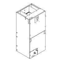
8. Pre-drill two clearance holes in the cabinet at dimples located
below the location the screws were removed for the coil support
brackets. There is one hole per side. See location of holes.
9. Replace the center horizontal bracket removed in Step 3. Use the
screws retained from Step 3 to attach.
10. Place coil support brackets into the lower set of slots and rotate
into place. Push downward to lock into place.
11. Secure each bracket with a screw that were previously removed.
Figure 7. All models
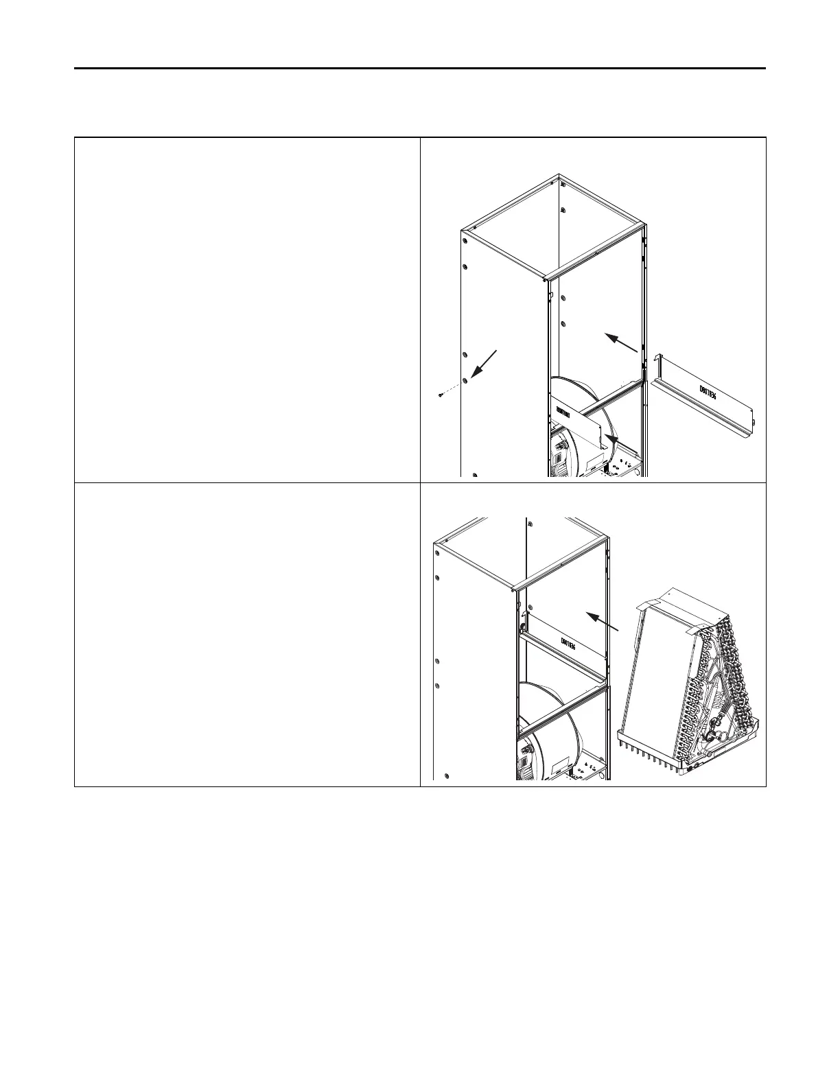
12. Slide the coil assembly back into the air handler cabinet as shown.
13. Remove the appropriate knock out for the condensate piping.
Figure 8. All models
CCooiill CCoonnvveerrssiioonn IInnssttrruuccttiioonnss