20
18-GF15D1-1B-EN
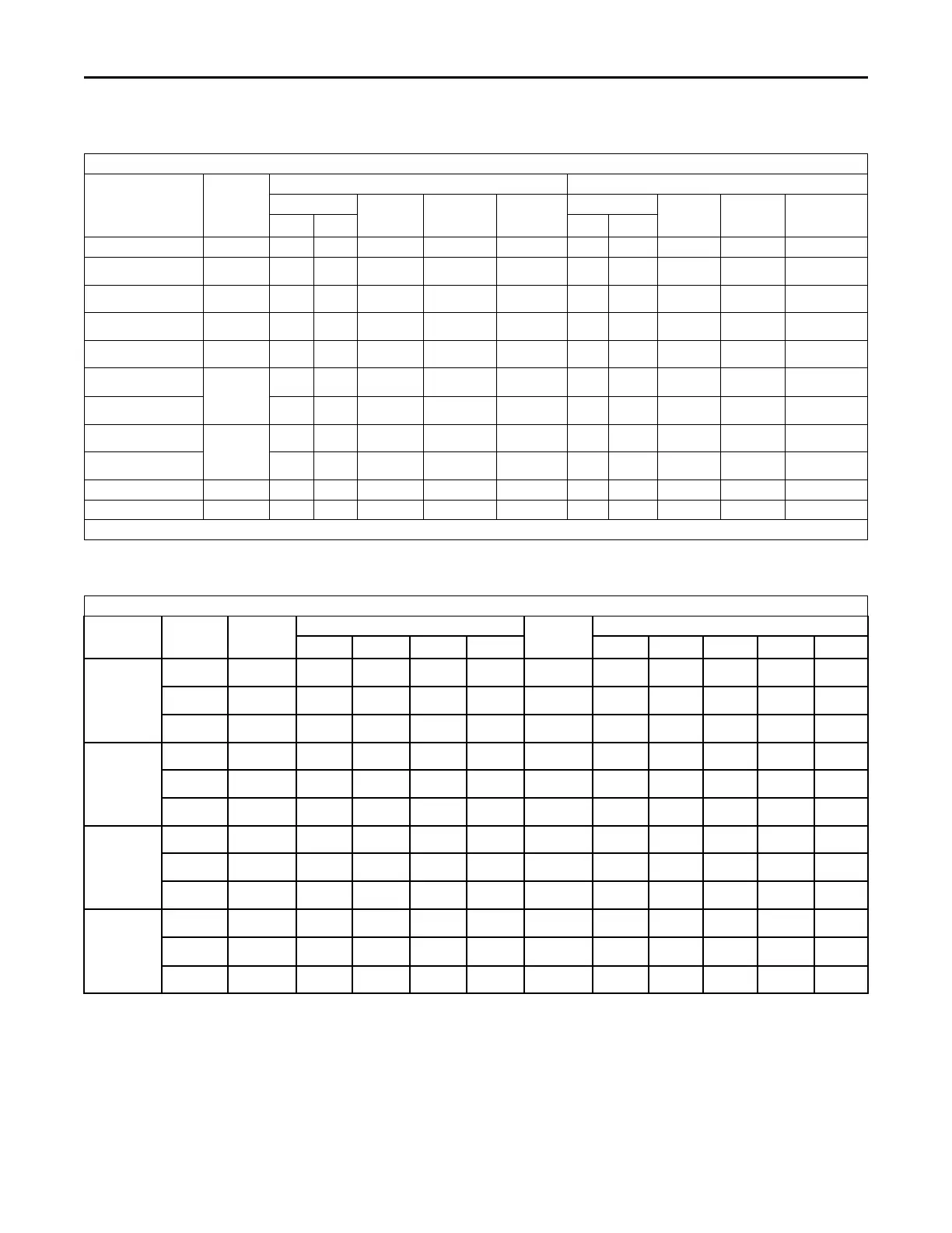
Table 20. Electrical Data
A4AH5V36A1C30A, A4AH5V42A1C30A HEATER DATA
Heater Model No.
No. of
Circuits/
Phases
240 Volt 208 Volt
Capacity
Heater
Amps per
Circuit
Minimum
Circuit
Ampacity
Maximum
Overload
Protection
Capacity
Heater
Amps per
Circuit
Minimum
Circuit
Ampacity
Maximum
Overload
Protection
kW BTUH kW BTUH
No Heater 4.3 * 5 15 4.3 * 5 15
BAYHTR1504BRK
BAYHTR1504LUG
1/1
3.84 13100 16.0 25 25 2.88 9800 13.8 23 25
BAYHTR1505BRK
BAYHTR1505LUG
1/1
4.80 16400 20.0 30 30 3.60 12300 17.3 27 30
BAYHTR1508BRK
BAYHTR1508LUG
1/1
7.68 26200 32.0 45 45 5.76 19700 27.7 40 40
BAYHTR1510BRK
BAYHTR1510LUG
1/1
9.60 32800 40.0 55 60 7.20 24600 34.6 49 50
BAYHTR1517BRK
Circuit 1
(a)
2/1
9.60 32800 40.0 55 60 7.20 24600 34.6 49 50
BAYHTR1517BRK
Circuit 2
4.80 16400 20.0 25 25 3.60 12300 17.3 22 25
BAYHTR1523BRK
Circuit 1
2/1
9.60 32800 40.0 55 60 7.20 24600 34.6 49 50
BAYHTR1523BRK
Circuit 2
9.60 32800 40.0 50 50 7.20 24600 34.6 43 45
BAYHTR3510LUG
1/3
9.60 32800 23.1 34 35 7.20 24600 20.0 30 30
BAYHTR3517LUG
1/3
14.40 49100 34.6 48 50 10.80 36900 30.0 42 45
* = Motor Amps
(a)
MCA and MOP for circuit 1 contains the motor amps
Table 21. Air Flow Performance
A4AH5V48A1C30A, A4AH5V60A1C30A COOLING AIRFLOW PERFORMANCE, WET COIL, NO FILTER, NO HEATER
OUTDOOR
UNIT SIZE
(TONS)
SPEED
SETTING
AIRFLOW
SETTING
DIP SWITCH SETTING
AIRFLOW
POWER
EXTERNAL STATIC PRESSURE
SW1 SW2 SW3 SW4 0.1 0.3 0.5 0.7 0.9
3
LOW
324 CFM/
ton
ON ON OFF ON
CFM
Watts
991
89
985
133
974
186
984
237
994
303
NORMAL
368 CFM/
ton
ON ON OFF OFF
CFM
Watts
1120
118
1119
167
1110
224
1116
279
1122
333
HIGH
423 CFM/
ton
ON ON ON OFF
CFM
Watts
1282
162
1286
219
1281
280
1280
343
1282
402
3.5
LOW
314 CFM/
ton
OFF ON OFF ON
CFM
Watts
1116
117
1114
165
1105
222
1111
277
1117
331
NORMAL
357 CFM/
ton
OFF ON OFF OFF
CFM
Watts
1263
156
1266
212
1261
273
1261
334
1263
392
HIGH
411 CFM/
ton
OFF ON ON OFF
CFM
Watts
1449
218
1458
287
1456
352
1449
421
1447
496
4
LOW
298 CFM/
ton
ON OFF OFF ON
CFM
Watts
1207
140
1208
193
1201
252
1203
311
1207
366
NORMAL
339 CFM/
ton
ON OFF OFF OFF
CFM
Watts
1368
190
1374
252
1370
315
1367
381
1367
448
HIGH
389 CFM/
ton
ON OFF ON OFF
CFM
Watts
1564
264
1577
343
1577
411
1567
484
1561
570
5
LOW
305 CFM/
ton
OFF OFF OFF ON
CFM
Watts
1534
251
1545
328
1545
394
1536
467
1531
550
NORMAL
(a)
347 CFM/
ton
OFF OFF OFF OFF
CFM
Watts
1740
344
1758
444
1762
518
1745
594
1734
684
HIGH
(b)
399 CFM/
ton
OFF OFF ON OFF
CFM
Watts
1995
484
2022
629
2030
717
2005
783
1987
828
(a)
Factory Default Setting
(b)
Airflow must not exceed 1800 cfm in horizontal right, horizontal left, and downflow applications due to condensate blowoff. The 5 ton high tap shall not be
used in these applications.
PPeerrffoorrmmaannccee aanndd EElleeccttrriiccaall DDaattaa
 Loading...