GF - D 8
Gas Valves
Step 22
For 24 volt applications, after manifold pressure setup
is complete, reset mode of operation back to 24 volt
[24VAC].
Step 20
Using a leak detection solution or soap suds, check
for leaks at plug or outlet pressure tap screw.
Step 21
For communicating applications, reconnect the
thermostat data line to the D terminal of the furnace
(Figure 19). Turn on the 115V power to the furnace.
With the thermostat data line connected to the furnace
and communications between the thermostat and the
furnace reestablished, the furnace operation will now
be controlled by the communicating comfort control.
Figure 19
Setting Manifold Pressure
Using Installer Test Mode
This method can only be used when a
communicating comfort control is being used.
To adjust the manifold pressure using Installer
Test mode on a communicating comfort control:
Step 1
If convenient, the communicating comfort control can
be accessed as it is installed in the home. If not
convenient, the communicating comfort control can
be attached directly at the furnace for this procedure
before moving it to its final installation location.
Step 2
Re-apply 115 VAC to the furnace.
Step 3
Set the communicating Comfort Control to Installer
Test #3 or #4 (Figure 20). See the Installer’s Guide of
the communicating comfort control. Note that the
communicating Comfort Control will remain in Installer
Test for five minutes only unless the user adjusts
something on the control before the end of five
minutes.
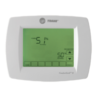
Figure 20
 Loading...