GF - D 14
Gas Valves
Step 20
Reconnect the thermostat data line to the D terminal
of the furnace (Figure 38). Turn on the 115V power to
the furnace. With the thermostat data line connected
to the furnace and communications between the
thermostat and the furnace reestablished, the furnace
operation will now be controlled.
Figure 38
Figure 36
Step 17
Remove 115 VAC power from the furnace. Do not
repower the furnace until the green LED on the inducer
motor drive board goes out (Figure 37).
Figure 37
Step 18
Turn the gas valve switch to the ON position. Remove
the field supplied manometer tubing and the tee
installed at the beginning steps and TIGHTEN DOWN
THE MANIFOLD DUST CAPS and the GAS
PRESSURE PORT SCREW.
Step 19
Using a leak detection solution or soap suds, check
for leaks at plug or outlet pressure tap screw.
Option 2
A) Simple
NOTE: Stage 1 = 40% (low) heat, Stage 2 = 100%
(high) heat
A qualified technician can cycle the Variable Speed
Indoor Blower and the Modulating Gas Furnace through
its operation at the User Interface.
• The unit test cycle is entered at the user interface.
• The test cycle can only be entered when the comfort
control has no demand and the furnace IFC is not
reporting a fault. Turn the comfort control to the
Off position and turn the fan control to Auto. This
will ensure the unit test cycle will not be interrupted.
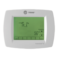
• Scroll down using the button at the user interface
until the display reads:
• UNIT TEST. Press the Enter button.
 Loading...