Do you have a question about the Trane Axiom GEHB 006 and is the answer not in the manual?
Manual purpose and scope.
Explains hazard symbols and warnings.
Procedures for checking units for shipping damage.
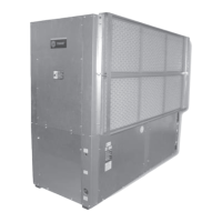
Details on unit nameplate, description, and coil construction.
Overview of available control system choices.
Role of thermostats and sensors in unit operation.
Tables detailing shipping and operating weights for units.
Visual guides for weight distribution for hanging GEH models.
Specifies service clearances for GEH models by tonnage.
Clearance dimensions for GEH 1/2-5 ton models.
Clearance dimensions for GEH 6-15 ton models.
Service clearances for GEV 1/2-5 ton models.
Minimum service clearances for GEV 6-10 ton models.
Unit service clearances for GEV 12.5-25 ton models.
Checklist summarizing essential steps for successful unit installation.
Covers main electrical, electric heat, and low voltage wiring.
Procedures for installing unit filters.
Instructions for connecting supply air ducts.
Instructions for connecting return air ducts.
Details on dual filtration design and accessory installation.
Converting to a ducted return air system with a panel.
Pad recommendation for noise reduction.
Steps for lifting and hanging horizontal units.
Guidance on installing proper condensate traps.
Connecting supply/return pipes and hose types.
Procedure for cleaning and flushing the unit's water loop.
Instructions for connecting water regulating valve assemblies.
Guidelines for field power wiring and safety.
Covers high voltage connection and safety.
Use and limitations of 24-volt control power transformers.
Guidance on ideal and unsuitable thermostat placement.
Explains AC control wiring requirements and conductor sizing.
Use of diagnostic LEDs for controller status.
Steps to modify blower motor RPM via speed-tap.
Adjusting airflow by modifying fan motor and sheave.
Steps for installing economizer on smaller GEH units.
Guides economizer installation on larger GEV/GEH models.
Step-by-step procedure for starting the unit with economizer.
Details on the three-way valve used in economizers.
Checklist of system devices to verify before unit energization.
Step-by-step guide for initial unit start-up.
Description of the unit's expected operational sequence.
Contractor checklist for unit verification during start-up.
Tables showing refrigerant pressures under various conditions.
Defines pressure drop and provides tables for calculation.
Provides water volume for calculating glycol requirements.
Guidance on filter inspection and replacement.
Ensuring condensate traps are primed.
Importance of checking water quality periodically.
Wiring diagram for basic 208V, 60Hz, 1-phase units.
Wiring diagram for deluxe 380-420V, 50Hz, 3-phase units.
Wiring diagram for ZN510 control units (208V, 60Hz, 1-phase).
Wiring diagram for ZN524 control units (460V, 60Hz, 3-phase).
Explanation of diagnostic LEDs for control troubleshooting.
Table mapping LED states to controller modes.
List of common problems, causes, and corrections.
Details the standard parts-only warranty terms.
Outlines optional extended warranty coverage.
| Brand | Trane |
|---|---|
| Model | Axiom GEHB 006 |
| Category | Water System |
| Language | English |