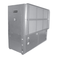
Do you have a question about the Trane Axiom GEVB 015 and is the answer not in the manual?
Explains the meaning of WARNING, CAUTION, and NOTICE symbols.
Instructions for checking components for shipping damage upon delivery.
Steps to verify unit data, power supply, and inspect for shipping damage.
Specifies required service clearances for GEH units.
Specifies required service clearances for GEV 1/2 through 5 ton units.
Specifies minimum service clearances for GEV 6 through 10 ton units.
Detailed measurements for various GEH unit configurations.
Detailed measurements for various GEH unit configurations.
Detailed measurements for various GEV unit configurations.
Detailed measurements for various GEV unit configurations.
Detailed measurements for various GEV unit configurations.
Detailed measurements for various GEV unit configurations.
Detailed measurements for various GEV unit configurations.
Detailed measurements for various GEV unit configurations.
Detailed measurements for various GEV unit configurations.
Detailed measurements for various GEV unit configurations.
Measurements for GEH 072-120 (60Hz) and GEH 072-090 (50Hz).
Measurements for GEH 072-120 (60Hz) and GEH 072-090 (50Hz).
Measurements for GEH 072-120 (60Hz) and GEH 072-090 (50Hz).
Measurements for GEH 072-120 (60Hz) and GEH 072-090 (50Hz).
Measurements for 6-10 ton (60Hz) and 6/7.5 ton (50Hz) units.
Measurements for 6-10 ton (60Hz) and 6/7.5 ton (50Hz) units.
Measurements for 6-10 ton (60Hz) and 6/7.5 ton (50Hz) units.
Measurements for 6-10 ton (60Hz) and 6/7.5 ton (50Hz) units.
Measurements for 20-25 ton (60Hz) and 15-20 ton (50Hz) units.
Measurements for 20-25 ton (60Hz) and 15-20 ton (50Hz) units.
Measurements for 20-25 ton (60Hz) and 15-20 ton (50Hz) units.
Measurements for 20-25 ton (60Hz) and 15-20 ton (50Hz) units.
Measurements for GEH units with waterside economizers.
Measurements for hanging units with waterside economizers.
Measurements for GEH units with right return economizers.
Measurements for GEH units with left return economizers.
Measurements for 6-10 ton (60Hz) and 6/7.5 ton (50Hz) economizers.
Measurements for GEV 12.5-25 ton units with economizers.
Outlines required service clearances for GEV 12 1/2 through 25 ton units.
Checklist summarizing essential steps for successful unit installation.
Procedures for verifying power supply and connecting main electrical wiring.
Instructions for installing the supply-air duct flange and collar.
Requirements for conforming power wiring to electrical codes.
Guidance on installing disconnect switches and high voltage connections.
Specific installation steps for economizers on larger GEH/GEV models.
Describes how the unit and economizer operate in heating and cooling modes.
Lists electrical data for GEH models 006, 009, 012, 015.
Lists electrical data for GEV 180, 240, 300 models.
A comprehensive checklist of pre-energization system checks.
Step-by-step guide for starting up the unit and economizer system.
Charts showing approximate refrigerant pressures and temperatures under various conditions.
Recommendations for regular maintenance, including filter checks.
A troubleshooting guide listing common problems, their causes, and solutions.
| Brand | Trane |
|---|---|
| Model | Axiom GEVB 015 |
| Category | Water System |
| Language | English |


 Loading...