ACC-SVN67D-EN 13
Installation
WARNING
Ground Wire!
All field-installed wiring must be completed by qualified personnel. All field-installed wiring must
comply with NEC and applicable local codes. Failure to follow this instruction could result in death
or serious injuries.
22. Wire according to the wiring diagram attached to the electric heater control panel door. Ground
unit at grounding lug provided on electric heater control panel assembly.
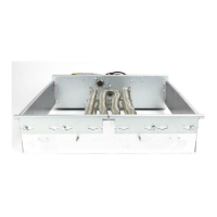
Important: After heater is installed and before applying power, verify that heating elements are
not damaged or pinched and that heating elements are not short circuited to each
other or to the heater frame or equipment cabinet by doing the following: Test every
heater element with ohmmeter and verify that heater element terminals are
electrically isolated from cabinet and ground (infinite resistance). On downflow
units with or without duct work installed or horizontal units without ductwork
installed, remove horizontal supply cover and carefully inspect elements after
installation for damage or proximity to supporting structure or cabinet. At least 1/4”
clearance is required around electric heater coils.
Important: Be sure to check tightness of all terminal connections, clamps, screws, etc., as these
may have become loose in shipment. Retighten all electrical connections after
equipment has been in operation and components have reached operating
temperature.
23. Install the magnets into the door as seen in Figure 8 or Figure 9. Magnets should lock into place
once installed. Close electric heater control panel access door, replace heat section access
panel and unit control box access panel. Replace horizontal supply cover. Be careful when
replacing cover and make sure gasketing is not torn or missing. Gasket must make water tight
seal.
24. Scratch out the square on unit nameplate showing heater model installed in unit.

 Loading...