CVHE-SVN04M-EN
29
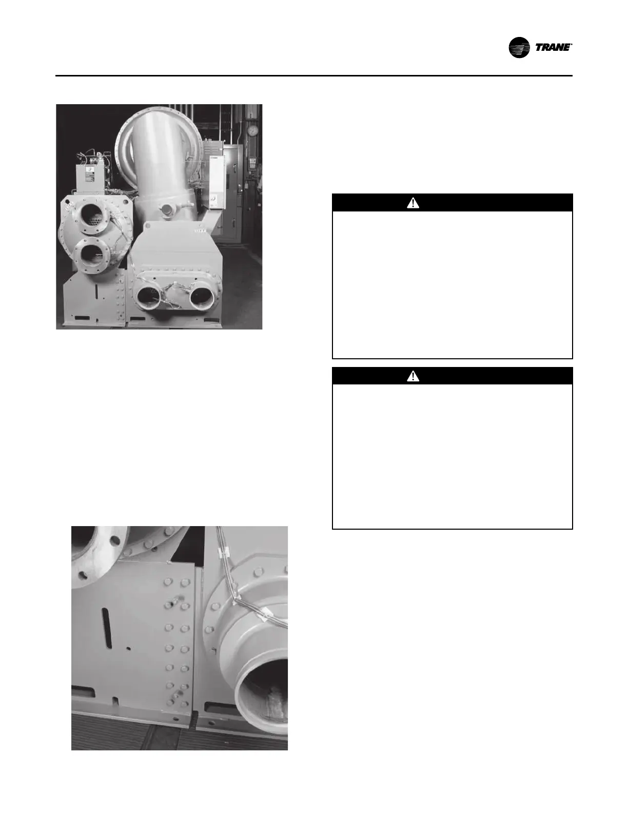
Figure 21. Separable shell unit (end view)
3. Remove the bolts from the flanges connecting the
evaporator tube sheet and condenser shell support
(see Figure 22, p. 29). Then remove the bolts from
the flanges connecting the shells.
NNoottee:: Some small shell combinations do not have
flanged connections between shells.
4. Remove the two dowel pins located in the flange on
each end of the shell tube sheet connections and lift
the condenser clear of the evaporator.
5. Reassemble the evaporator and condenser shells in
the reverse order.
6. Torque all bolts to specifications listed in Table 13,
p. 32.
Figure 22. Separable shell unit (flange connection)
Disassembly of Chillers with
Options
Heat Recovery
Use the following steps when disassembling chillers
with auxiliary or heat recovery condenser shells to
reduce the vertical clearance required for the chiller
installation.
WWAARRNNIINNGG
RReeffrriiggeerraanntt MMaayy BBee UUnnddeerr PPoossiittiivvee
PPrreessssuurree!!
FFaaiilluurree ttoo ffoollllooww iinnssttrruuccttiioonnss bbeellooww ccoouulldd rreessuulltt iinn
aann eexxpplloossiioonn wwhhiicchh ccoouulldd rreessuulltt iinn ddeeaatthh oorr
sseerriioouuss iinnjjuurryy oorr eeqquuiippmmeenntt ddaammaaggee..
SSyysstteemm ccoonnttaaiinnss rreeffrriiggeerraanntt aanndd mmaayy bbee uunnddeerr
ppoossiittiivvee pprreessssuurree;; ssyysstteemm mmaayy aallssoo ccoonnttaaiinn ooiill..
RReeccoovveerr rreeffrriiggeerraanntt ttoo rreelliieevvee pprreessssuurree bbeeffoorree
ooppeenniinngg tthhee ssyysstteemm.. SSeeee uunniitt nnaammeeppllaattee ffoorr
rreeffrriiggeerraanntt ttyyppee.. DDoo nnoott uussee nnoonn--aapppprroovveedd
rreeffrriiggeerraannttss,, rreeffrriiggeerraanntt ssuubbssttiittuutteess,, oorr nnoonn--
aapppprroovveedd rreeffrriiggeerraanntt aaddddiittiivveess..
WWAARRNNIINNGG
HHeeaavvyy OObbjjeecctt!!
FFaaiilluurree ttoo ffoollllooww iinnssttrruuccttiioonnss bbeellooww ccoouulldd rreessuulltt iinn
uunniitt ddrrooppppiinngg wwhhiicchh ccoouulldd rreessuulltt iinn ddeeaatthh oorr
sseerriioouuss iinnjjuurryy,, aanndd eeqquuiippmmeenntt oorr pprrooppeerrttyy--oonnllyy
ddaammaaggee..
EEnnssuurree tthhaatt aallll tthhee lliiffttiinngg eeqquuiippmmeenntt uusseedd iiss
pprrooppeerrllyy rraatteedd ffoorr tthhee wweeiigghhtt ooff tthhee uunniitt bbeeiinngg
lliifftteedd.. EEaacchh ooff tthhee ccaabblleess ((cchhaaiinnss oorr sslliinnggss)),, hhooookkss,,
aanndd sshhaacckklleess uusseedd ttoo lliifftt tthhee uunniitt mmuusstt bbee ccaappaabbllee
ooff ssuuppppoorrttiinngg tthhee eennttiirree wweeiigghhtt ooff tthhee uunniitt.. LLiiffttiinngg
ccaabblleess ((cchhaaiinnss oorr sslliinnggss)) mmaayy nnoott bbee ooff tthhee ssaammee
lleennggtthh.. AAddjjuusstt aass nneecceessssaarryy ffoorr eevveenn uunniitt lliifftt..
1. Support the auxiliary or heat recovery condenser
with rigging using the lifting holes on the tube
sheets. Do not lift the shell; simply support it to
avoid slipping as the bolts are removed from the
connecting flanges.
2. Remove the bolts from the flanges on the
interconnecting piping and flanges connecting the
auxiliary heat recovery condenser and condenser
tube sheets.
3. Remove the bolts from the flanges on the
interconnecting piping and the flanges connecting
the shells.
4. Lift the condenser clear of the unit.
5. Reassemble the condenser in the reverse order.
Install new gaskets at the appropriate joints.
6. Torque all bolts to torque specifications listed in
Table 13, p. 32.
DDiissaasssseemmbbllyy
 Loading...


