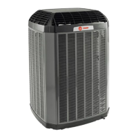
Do you have a question about the Trane ComfortLink II 4TWZ0036B1000A and is the answer not in the manual?
| Model Number | 4TWZ0036B1000A |
|---|---|
| Category | Heat Pump |
| Brand | Trane |
| Series | ComfortLink II |
| Nominal Capacity (Tons) | 3 |
| Cooling Capacity (BTU/h) | 36000 |
| SEER Rating | Up to 18 |
| HSPF Rating | Up to 10 |
| Refrigerant Type | R-410A |
| Voltage (V) | 208/230 |
| Phase | 1 |
| Heating Capacity (BTU/h) | 36000 |
| Warranty | 10 Years |
Detailed technical specifications for the outdoor unit and components.
Specifications for refrigerant line tubing sizes and lengths.
Electrical schematic and equipment legend for system wiring.
Procedures for manual and Charge Assist™™ charging.
Detailed wiring diagram for system components and connections.
Chart for manual charging based on liquid gauge pressure and temperature.
Steps to use Charge Assist™ with a communicating control system.
Detail of the Charge Assist™ circuit board and its components.
Explains the CHARGED, ADD, and RECOVER routines based on LED indicators.
Information on the required solenoid kit for automated charging.
Steps for using Charge Assist™ with non-communicating controls.
Table summarizing fault codes and Charge Assist™ LED statuses.
Detailed explanation of LED indicators for system status and faults.
Table detailing LED flash rates and their meanings.
Graphs showing discharge and suction pressures for cooling mode.
Graphs showing discharge and suction pressures for heating mode.
Diagram illustrating the refrigeration flow in heating mode.
Diagram illustrating the refrigeration flow in cooling mode.
Identifies test points on the control board for voltage checks.
Tables for ECM fan signals and sump heat control.
Resistance and voltage data for ambient and coil sensors.
Data for liquid line temperature sensor and pressure transducer.
Explanation of the Status and Fault LEDs on the EEV board.
Lists EEV fault codes and important operational notes.
A flowchart to diagnose EEV operational issues.
Identification of test points on the EEV control board.
Instructions for performing Close Valve and Open Valve tests.
Resistance and voltage data for the suction line temperature sensor.
Voltage data corresponding to pressure readings for the suction line transducer.


 Loading...