Do you have a question about the Trane Variable Speed ComfortLink II 4TWV8024A1000B and is the answer not in the manual?
Covers hazardous voltage, refrigerant oil, contains refrigerant, high leakage current, and grounding.
Addresses hot surfaces, service valve handling, and brazing precautions.
Warning about dangerous DC voltage in components after power disconnection.
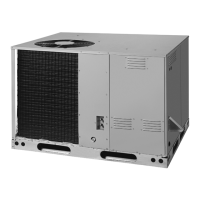
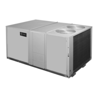
Details physical dimensions and weights for various outdoor unit models.
Specifies required sizes for vapor and liquid refrigerant lines and service valve connections.
Provides recommendations for optimal unit placement and clearances.
Recommendations for unit placement to ensure optimal performance and avoid issues like snow.
Precautions for installing heat pumps in areas prone to snow and freezing temperatures.
Requirements for units installed within one mile of salt water.
Instructions for inspecting the unit for shipping damage and removing it from the pallet.
Guidelines for proper installation of the support pad for the outdoor unit.
Guidance on determining the necessary refrigerant line length and vertical change.
Importance and method of insulating vapor and liquid refrigerant lines.
Precautions and guidelines for reusing existing refrigerant lines in retrofit applications.
Best practices for routing refrigerant lines, including isolation and minimizing turns.
Methods for isolating refrigerant lines from structural elements like joists and rafters.
Guidelines for isolating refrigerant lines within wall cavities.
Procedures for properly routing and sealing refrigerant lines through walls.
Steps for removing caps, deburring, cleaning lines, and purging with nitrogen.
Details on brazing lines to valves, handling external driers, and replacing valve cores.
Steps for pressurizing lines with nitrogen and checking for leaks using a soapy solution.
Procedure for evacuating the system to a specific micron level for dryness.
Explanation of when and how to use the Weigh-In method for system charging.
Worksheet and steps to calculate refrigerant charge for new systems using weigh-in.
Worksheet and steps to calculate refrigerant charge for system repairs using weigh-in.
Procedure for opening the gas service valve after leak check and evacuation.
Procedure for opening the liquid service valve, emphasizing caution due to pressure.
Details on wire size, maximum length, and recommendations for low voltage wiring.
Illustrates wiring connections for a fully communicating system.
Safety warnings and compliance requirements for high voltage power supply.
Guidelines for installing a separate disconnect switch and using flexible conduit.
Identifies the location of Status and COMM LEDs on the control board.
Explains the meaning of various LED rates and states for Status (Green) and COMM (Amber).
Ensures prior sections are completed, thermostat is OFF, and power is applied.
Instructions for waiting periods and running the "Charging Mode-Cooling" for system charge.
Specifies required outdoor and indoor temperature ranges for subcooling charging.
Worksheet to determine final subcooling value using line length, lift, and design subcooling.
Charts providing subcooling corrections based on line length and lift for different tonnage units.
Table correlating liquid temperature with design subcooling and liquid gauge pressure.
Steps to attain proper gage pressure by adding or recovering refrigerant based on the charging chart.
Waiting period for system stabilization after adjustments and removing gauges.
Directs users to Service Facts for system pressure curves to verify performance.
Fields to record critical system parameters after charging is complete.
Explains how to navigate the CDA menus (Monitor, Alert, Config, Control).
Details specific tests and settings available within the Technician Menus.
Explanation of how demand defrost measures ambient and coil temperatures to initiate defrost.
Describes the conditions for initiating and terminating the defrost cycle.
Instructions for manually initiating a forced defrost cycle via the CDA.
A comprehensive list of checks to confirm proper installation and system function.