CG-SVX027E-GB
20
4 UNT-PRC002-GB
Technical Data
FWD 08 12 20 30 45
Power supply (V/Ph/Hz) 230/1/50
Capacities
Cooling capacity on water (1) (kW) 5,2 8,3 15 18,8 30,1
Heating capacity on water (2) (kW) 6,3 11,9 18,9 20,9 38,2
Fan motor (type) 2 x direct drive centrifugal
Fan power input (3) (kW) 0,23 0,46 0,65 1,04 1,51
Current amps (3) (A) 1,1 2,2 3,1 4,7 5,5
Start-up amps (A) 3,2 5,5 9,3 14,1 16,5
Air flow
minimum (m
3
/h) 490 980 1400 1800 2700
nominal (m
3
/h) 820 1650 2300 3000 4500
maximum (m
3
/h) 980 1970 2600 3600 5400
Main coil
Water entering/leaving connections (type) ISO R7 rotating female
(Dia) 3/4" 3/4" 1 1/2" 1 1/2" 1 1/2"
Electric heater (accessory for blower only)
Electric power supply (V/Ph/Hz) 230/1/50 230/1/50 or 400/3/50 400/3/50 400/3/50 400/3/50
Heating capacity (kW) 2/4 8 10 12 12
Hot water coil (accessory for blower only)
Heating capacity (4) (kW) 6,3 12 17,4 22,4 34,5
G2 filter (filter box accessory)
Quantity 2 2 2 2 2
Dimensions ( LxWxth) (mm) 386x221x8 486x271x8 586x321x8 586*421*8 586*621*8
G4 filter (filter box accessory)
Quantity - 2 2 2 2
Dimensions ( LxWxth) (mm) - 486x264x48 586x314x48 586*414*48 586*614*48
Condensate pump (accessory) (type) Centrifugal
Water flow - lift height (l/h - mm) 24 - 500
Not available for FWD30 and FWD45
Sound level (L/M/H speed)
Sound pressure level (5) (dB(A)) 36/40/43 38/41/44 46/50/53 47/52/57 47/52/58
Sound power level (5) (dB(A)) 46/50/53 48/51/54 56/60/63 57/62/67 57/62/68
Unit dimensions
Width x Depth (mm) 890 x 600 1090 x 710 1290 x 820 1290 x 970 1290 x 1090
Height (mm) 250 300 350 450 650
Shipped unit dimensions
Width x Depth (mm) 933 x 644 1133 x 754 1333 x 864 1333 x 1008 1333*1133
Height (mm) 260 310 360 460 660
Weight (kg) 32 46 61 76 118
Colour galvanised steel
Recommended fuse size
Unit alone (aM/gI) (A) 8/16 8/16 8/16 8/25 8/25
Unit with electric heater (gI) (A) 16 (2kW),25 (4kW) 40 (230V),3*16 (400V) 3*20 3*25 3*25
(1) Conditions: Water entering/leaving temperature: 7/12 °C, Air inlet temperature 27/19°C DB/WB - Nominal air flow
(2) Conditions: Water entering/leaving temperature: 50/45 °C, Air inlet temperature 20°C DB - Nominal air flow
(3) At high speed with nominal air flow.
(4) Water entering/leaving temperature 90/70 °C, air inlet temperature 20 °C DB, Nominal air flow.
(5) A rectangular glass wool duct 1m50 long is placed on the blower.The measurement is taken in the room containing the blower unit.
Heat exchanger operating limits:
FWD:
*water temperature: max 100° C
*absolute service pressure: min 1 bar/max 11 bars
Accessories - Hot water coil:
*water temperature: min. +2° C/max. 100° C
*absolute service pressure: min 1 bar/max 11 bars
Installation – Mechanical
Drainage
Locate the unit near a large capacity drain for water
vessel draindown during shutdown or repair. Water
piping is provided with drain connections. Refer to
“Water Piping.” All local and national codes apply.
Piping
A vent is provided on the top of the evaporator at the
return end. Be sure to provide additional vents at high
points in the piping to bleed air from the chilled water
system. Install necessary pressure gauges to monitor the
entering and leaving chilled water pressures.
Provide shutoff valves in lines to the gauges to isolate
them from the system when they are not in use. Use
rubber vibration eliminators to prevent vibration
transmission through the water lines. If desired, install
thermometers in the lines to monitor entering and
leaving water temperatures. Install a balancing valve
in the leaving water line to control water ow balance.
Install shutoff valves on both the entering and leaving
water lines so that the evaporator can be isolated
for service. Make sure the water circuit includes all
devices and controls used to provide proper water
system operation and unit operating safety. Refer to the
appropriate sections in the unit manual (Addendum_
PROD-SVX01) for Installation, appropriate procedures,
component specications and safety instructions.
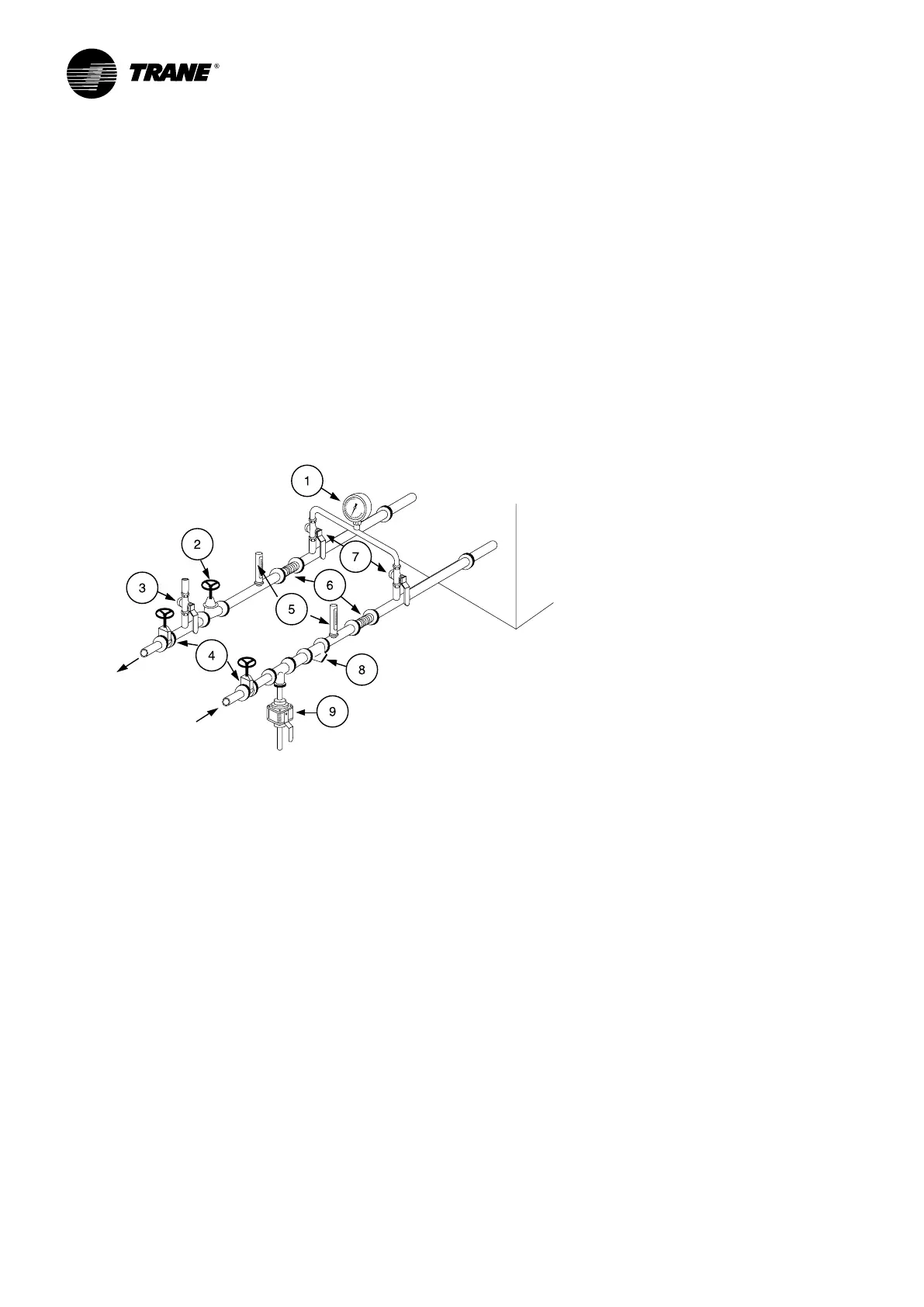
Figure 3 - Unit typical water circuit
1 = Pressure gauges: show entering and leaving water
pressure
2 = Balancing valve: adjusts water ow.
3 = Air purge allows to remove the air from the water
circuit during ll up.
4 = Stop valves: isolate chillers and water circuiting
pump during maintenance operations.
5 = Thermometers: indicate chilled water entering and
leaving temperatures.
6 = Expansion compensators: avoid mechanical stress
between chiller and piping installation.
7 = Stop valve located on the outlet connection: used
to measure the water pressure inlet or outlet of
evaporator.
8 = Strainer: avoid to get heat exchangers dirty. All
installation must be equipped with efcient strainer
in order that only clean water enters into exchanger.
If there is no strainer, reserve will be formulated by
the Trane technician at the start-up of the unit. The
trainer used must be able to stop all particles with a
diameter greater than 1 mm.
9 = Draining: used as the draining the plate heat
exchanger.
10 = Do not start the unit with low water volume or not
enough pressurized circuit.
Note: A pressure switch device to detect lack of water
is not included in the pump package. Installation of this
type of device is highly recommended to avoid sealing
damage due to operation of pump without enough
water.
Minimal installation water content
The water volume is an important parameter because
it allows as table chilled water temperature and avoids
short cycle operation of the compressors.
Parameters which influence the water temperature
stability
• Water loop volume
• Load uctuation
• Number of capacity steps
• Compressors rotation
• Dead band (adjusted on chiller controller)
• Minimum time between 2 starts of a compressor
Minimum water volume for a comfort application
For comfort application we can allow water temperature
uctuation at part load. The parameter to take
into account is the minimum operating time of the
compressor. In order to avoid lubrication problem
on a scroll compressor it must run at least 2 minutes
120 seconds) before it stops.

 Loading...