CG-SVX027E-GB
43
11UNT-PRC002-GB
Sound power levels
Discharge
Measurement conditions:
Measurements taken in a room adjacent to the room containing the FWD, at the outlet of the rectangular duct (1.5 m
long) fixed to its discharge opening.
Fan Power level in dB(A), per Hz frequency band Overall power
Unit speed 125 250 500 1000 2000 4000 8000 dB(A)
1 55 50 42 37 37 31 30 46
FWD 08 2 57 54 47 40 30 38 40 50
3 58 57 50 42 32 40 43 53
1 57 51 45 42 34 33 28 48
FWD 10 2 58 54 48 45 38 39 35 51
3 60 58 50 48 40 42 39 54
1 57 51 45 42 34 33 28 48
FWD 12 2 58 54 48 45 38 39 35 51
3 60 58 50 48 40 42 39 54
1 56 62 50 48 39 38 36 56
FWD 14 2 61 66 55 53 47 46 45 60
3 63 69 58 56 50 50 49 63
1 57 63 51 49 40 39 37 57
FWD 20 2 61 66 55 53 47 46 45 60
3 63 69 58 56 50 50 49 63
Intake
Measurement conditions:
Measurements taken at the horizontal air intake.
Fan Power level in dB(A), per Hz frequency band Overall power
Unit speed 125 250 500 1000 2000 4000 8000 dB(A)
1 56 55 55 53 46 45 42 57
FWD 08 2 63 62 60 60 53 53 53 64
3 66 65 63 62 56 55 57 67
1 62 58 55 58 51 48 44 61
FWD 10 2 66 63 60 62 56 55 52 66
3 70 67 63 65 59 59 57 69
1 62 58 55 58 51 48 44 61
FWD 12 2 66 63 60 62 56 55 52 66
3 70 67 63 65 59 59 57 69
1 66 65 65 65 57 50 46 68
FWD 14 2 73 72 69 71 64 59 57 74
3 78 76 73 75 69 64 63 78
1 68 72 64 64 56 52 50 69
FWD 20 2 76 76 68 71 65 61 61 75
3 78 79 71 74 69 66 66 78
General Start up
Start Up
Follow the instructions below to correctly start-up the
unit.
Installation and chiller inspection
• Ensure that all the operations above (start-up
preparation), are followed. Follow the instruction stuck
inside the electrical cabinet
• Put the plexiglass supplied by Trane in front of the
power terminal
• Ensure all water and refrigerant valves are in service
positions. When ball valve is present on the refrigerant
suction line, to check if the valve is open before
starting the unit.
• Ensure that the unit is not damaged
• Ensure that sensors are properly installed in their bulb-
wells and submerged in heat conducting product
• Check xing of capillary tubes (protection from
vibration and from wear) and ensure that they are not
damaged
• Reset all manually set control devices
• Check refrigerating circuits tightness
Checking and setting
Compressors
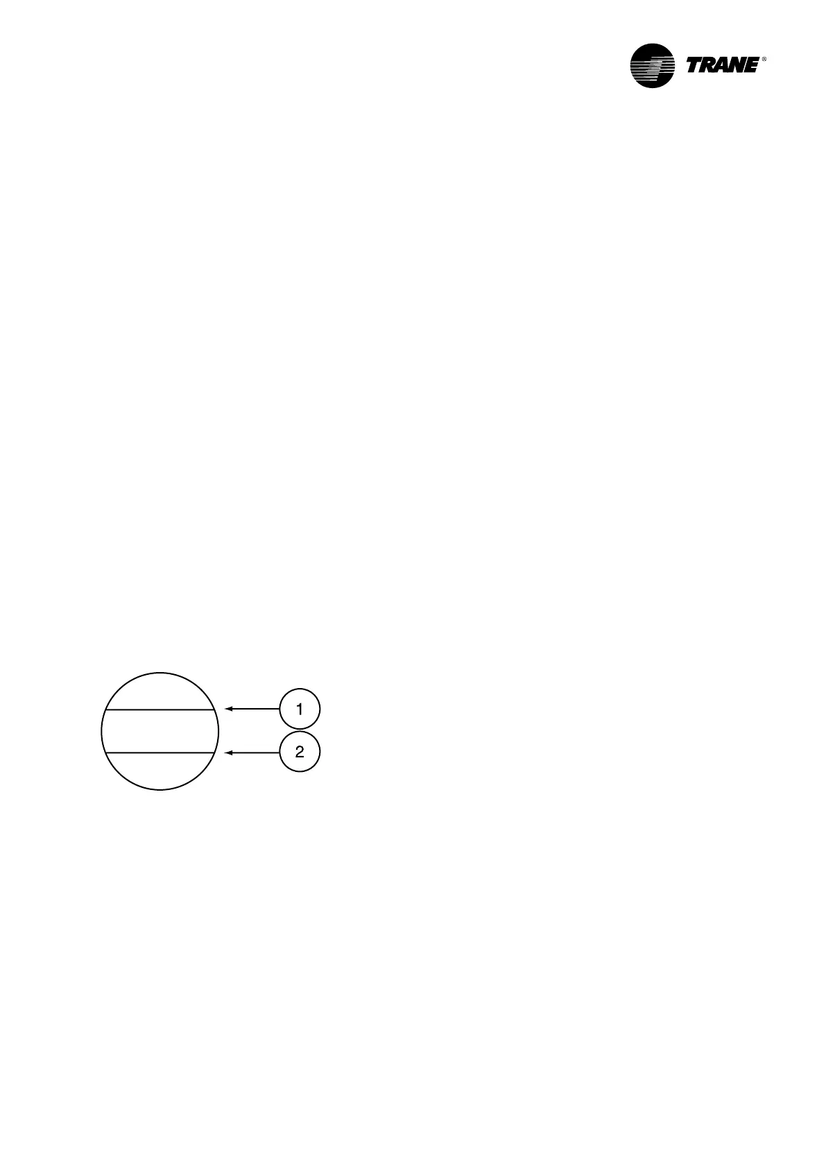
• Check oil level at rest. The level should reach at least
halfway up indicator located on housing. See Figure 16
for correct level.
Figure 13 - Compressor oil level
1 = Max. oil level
2 = Min. oil level
• Reset all manually set control devices
• Check refrigerating circuits tightness
• Check electrical terminals tightening of the motors and
in the control panel
• Check the isolation of the motors using a 500V
DC megohmeter which meets manufacturer’s
specications (minimum value 2 megohms)
• Check the direction of the rotation using phasemeter
Electrical power wiring
• Check all the electrical terminals tightening
• Set-up compressors overload relays
• Set-up fan-motors overload relays
Electrical control wiring
• Check all the electrical terminals tightening
• Check all the pressostats
• Check and set-up the chiller unit control module
• Test and start-up without the electrical power
Condenser
• Check direction of the rotation of fans
• Check the isolation of the motors using a 500V
DC megohmeter which meets manufacturer’s
specications (minimum value 500 megohms)
Operating parameters statement
• Switch on main power supply switch
• Start the water pump(s) and check there is no
cavitation
• Start-up the unit following procedure described in the
CH535 controller user guide. The unit and the chilled
water pumps contactor must be connected together
• After unit start up, leave in operation for at least
15 minutes, to ensure pressures are stabilized
Then check:
• voltage
• compressors and fan-motors currents
• leaving and return chilled water temperature
• suction temperature and pressure
• ambient air temperature
• blowing air temperature
• discharge pressure and temperature
• liquid refrigerant temperature and pressure
• operating parameters
• chilled water pressure drop through
evaporator (if no hydraulic module is installed)
or unit available pressure. It must be in
accordance with Trane order write-up
• superheat: difference between suction
temperature and dew point temperature.
Normal superheat should be within 5 and 7 °C
with R410A in cooling mode
• sub-cooling: difference between liquid
temperature and bubble point temperature.
Normal sub-cooling should be within 2 and
15°C with R410A in cooling mode
• difference between dew point temperature
in high pressure and condenser air inlet
temperature. Normal value on standard unit
with R410A should be 15 to 23°C
• difference between outlet water temperature
and dew point temperature in low pressure.
Normal value on standard unit, without
Ethylene glycol in chilled water, should be
about 3.5°C

 Loading...