CG-SVX027E-GB
9
11UNT-PRC002-GB
Sound power levels
Discharge
Measurement conditions:
Measurements taken in a room adjacent to the room containing the FWD, at the outlet of the rectangular duct (1.5 m
long) fixed to its discharge opening.
Fan Power level in dB(A), per Hz frequency band Overall power
Unit speed 125 250 500 1000 2000 4000 8000 dB(A)
1 55 50 42 37 37 31 30 46
FWD 08 2 57 54 47 40 30 38 40 50
3 58 57 50 42 32 40 43 53
1 57 51 45 42 34 33 28 48
FWD 10 2 58 54 48 45 38 39 35 51
3 60 58 50 48 40 42 39 54
1 57 51 45 42 34 33 28 48
FWD 12 2 58 54 48 45 38 39 35 51
3 60 58 50 48 40 42 39 54
1 56 62 50 48 39 38 36 56
FWD 14 2 61 66 55 53 47 46 45 60
3 63 69 58 56 50 50 49 63
1 57 63 51 49 40 39 37 57
FWD 20 2 61 66 55 53 47 46 45 60
3 63 69 58 56 50 50 49 63
Intake
Measurement conditions:
Measurements taken at the horizontal air intake.
Fan Power level in dB(A), per Hz frequency band Overall power
Unit speed 125 250 500 1000 2000 4000 8000 dB(A)
1 56 55 55 53 46 45 42 57
FWD 08 2 63 62 60 60 53 53 53 64
3 66 65 63 62 56 55 57 67
1 62 58 55 58 51 48 44 61
FWD 10 2 66 63 60 62 56 55 52 66
3 70 67 63 65 59 59 57 69
1 62 58 55 58 51 48 44 61
FWD 12 2 66 63 60 62 56 55 52 66
3 70 67 63 65 59 59 57 69
1 66 65 65 65 57 50 46 68
FWD 14 2 73 72 69 71 64 59 57 74
3 78 76 73 75 69 64 63 78
1 68 72 64 64 56 52 50 69
FWD 20 2 76 76 68 71 65 61 61 75
3 78 79 71 74 69 66 66 78
Pre-Installation
Installation requirements and contractor responsibilities
A list of the contractor responsibilities typically associated with the unit installation process is provided.
Type of requirement
Trane factory Supplied Trane factory Supplied Field supplied
Trane factory Installed Field Installed Field installed
Foundation Meet foundation requirements
Rigging
• Safety chains
• Clevis connectors
• Lifting beams
Isolation Neoprene pads (Optional)
Isolators
(customer supplied)
Electrical
• Disconnect Switch
• Unit mounted starter
• Wiring sizes per submittals and local codes
and regulations
• Terminal lugs
• Control voltage wiring
• Ground connection(s)
• BAS Wiring (optional)
• Chilled water pump contactor and wiring
including interlock
• Option relays and wiring
Water piping
• Taps for thermometers and gauges
• Thermometers
• Waterowpressuregauges
• Isolation and balancing valves in water
piping
• Vents and rains
• Pressure relief valves
• Pressure switch device to detect lack of
water
Insulation • Insulation • Insulation (piping)
Water piping connection elements • Grooved pipe
• Grooved pipes coupling
and stub pipe (Optional)
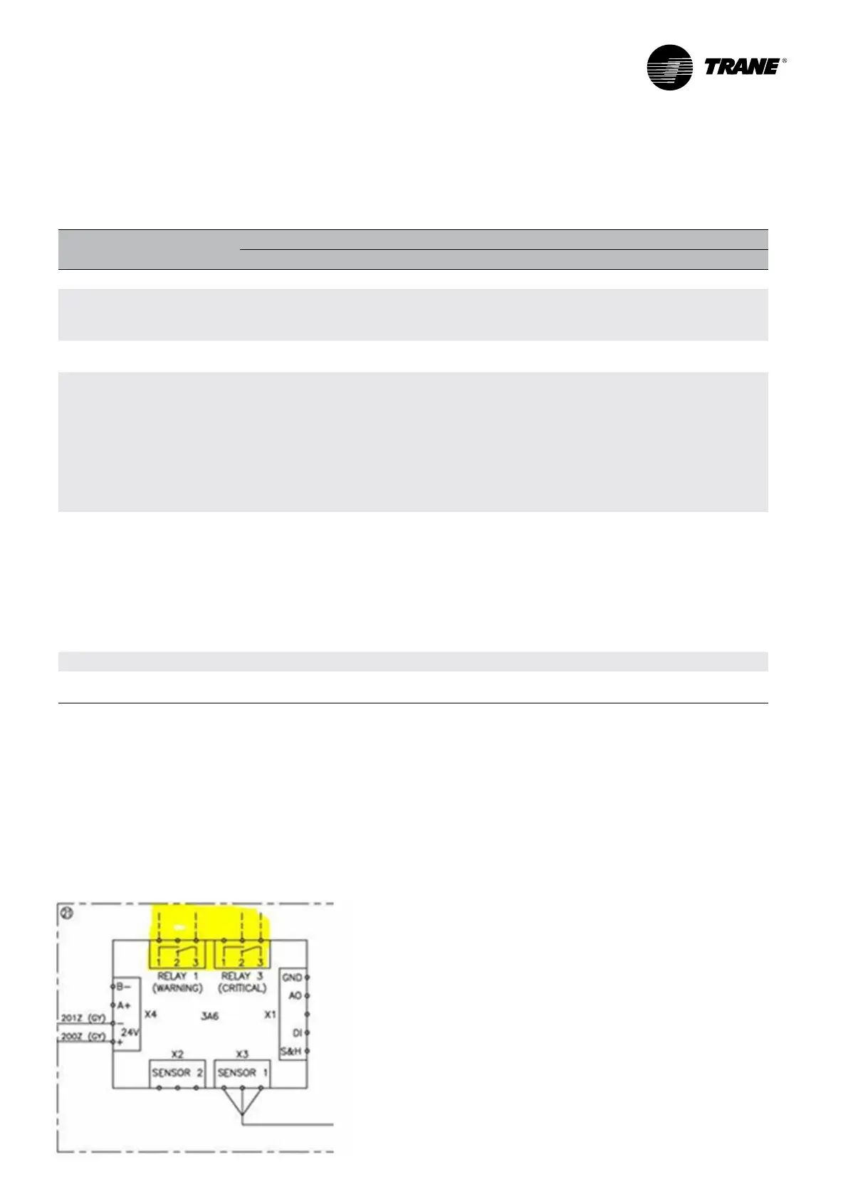
Refrigerant leak detector R454B
Refrigerant leak detector R454B is an option available only for R454B units. It is installed in the factory and set
according to the critical thresholds but it is not wired.
There are two relays available: Relay 1 for warning message and Relay 3 for critical message. When warning or
critical levels of R454B concentrations are reached, customer has to shutdown the electrical power to the unit.
It is needed to use a disconnect switch upstream from the unit, operated remotely, that will open electric circuit to
the unit when there is a refrigerant leakage. Please consult wiring diagrams regarding to the relay’s connection. The
refrigerant detector is identied as 3A6.

 Loading...