CVGF-SVN02B-E4
35
Installation:
Mechanical
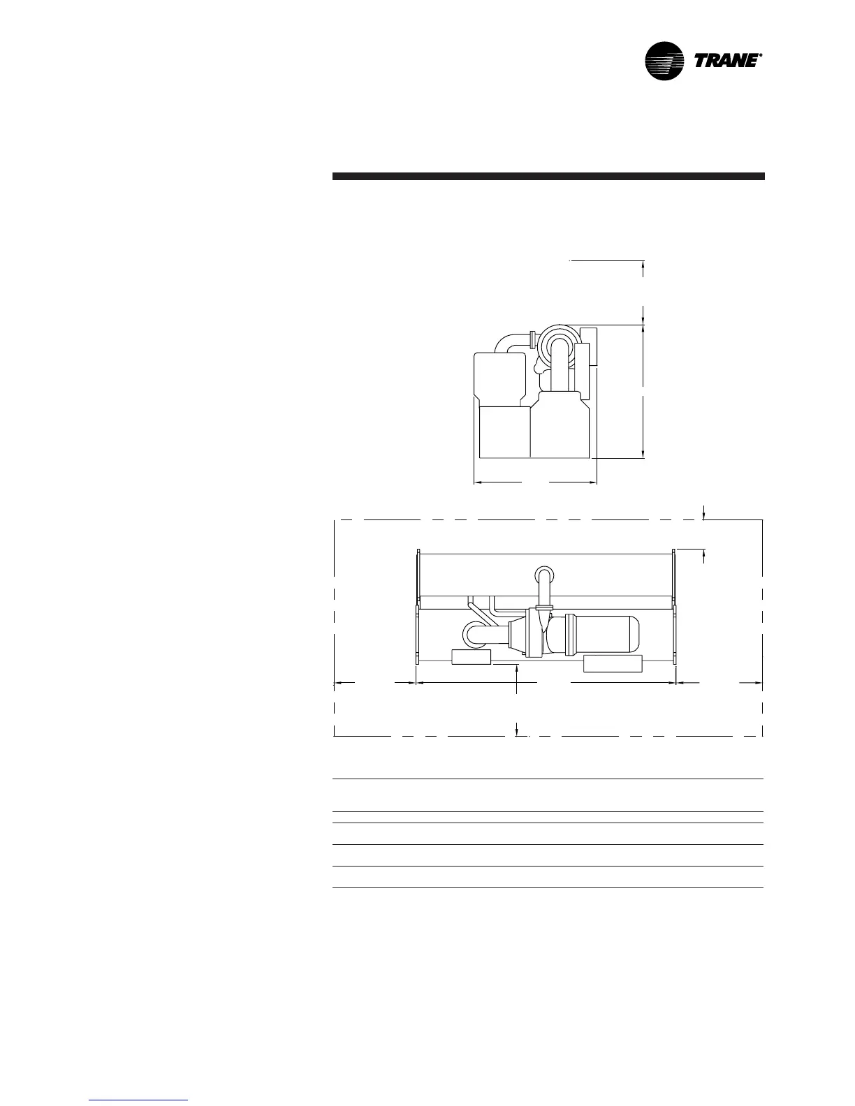
Figure 5. Recommended operating and service clearances –
Model CVGF without unit-mounted starters
36" (914 mm)
Recommended
clearance
Height
Width
18" (457 mm)
Recommended
clearance
CL1/CL2
Length
CL1/CL2
36" (914 mm)
Recommended
clearance
Table 8. Dimensions for figure 5
Clearance Tube Pull
Feet-Inch (mm)
Compressor Shell Size CL1 CL2 Length Height Width
400-500 500 13' 11" 3' 7" 13' 5" 6' 11" 6' 3"
(4.235) (1.092) (4.083) (1.790) (1.913)
560-700 700 13' 11" 3' 7" 13' 5" 6' 11" 6' 7"
(4.235) (1.092) (4.083) (1.790) (2.028)
740-1000 1000 13' 11" 3' 7" 13' 5" 8' 4" 7' 5"
(4.235) (1.092) (4.083) (2.540) (2.261)
Notes:
CL1 at either end of the machine and is required for tube pull clearance.
CL2 is always at the opposite end of the machine from CL1 and is required for service clearance.
Add 14-5/8" (37.1 cm) on each end for the water box.
Unit Dimensions Without Unit
Mounted Starters
Dimensions Feet-Inch (m-meters)