Cooling Cycle
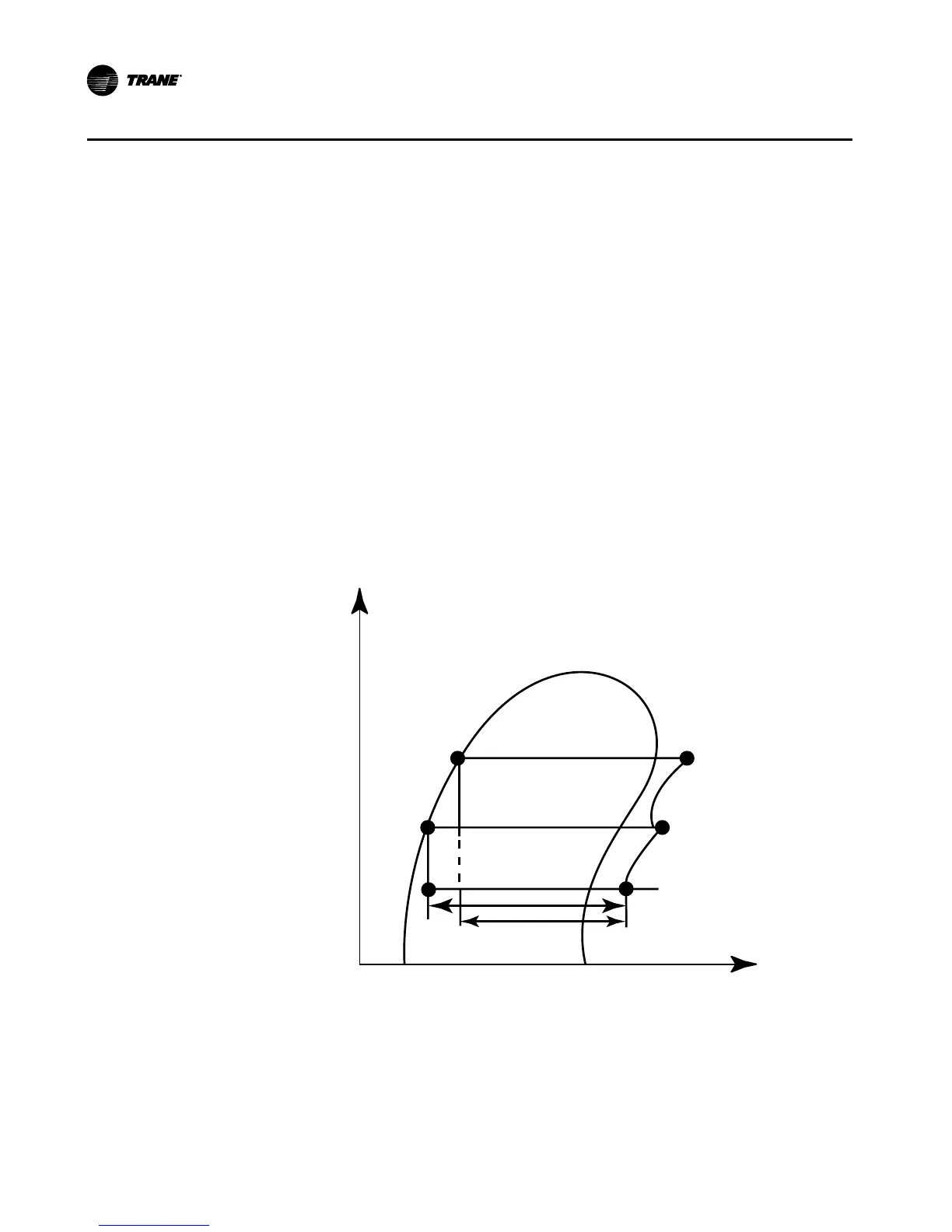
The refrigeration cycle of the CVGF chiller can be described using the pressure-enthal-
py diagram shown in Figure 4. Key state points are indicated and will be referred to in
the following discussion. A schematic of the system showing refrigerant flow is given
in Figure 5.
Evaporator -
A liquid vapor refrigerant mixture enters the evaporator at state point 1. Liquid refrig-
erant is vaporized to state point 2 as it absorbs heat from the system cooling load.
The vaporized refrigerant flows into the compressor first stage.
Compressor first stage -
Refrigerant vapor is drawn from the evaporator into the first stage compressor. The
first stage impeller accelerates the vapor increasing its temperature and pressure to
state point 3.
Figure 4. P-H chart