AFDH-SVN01A-EN 41
Installation
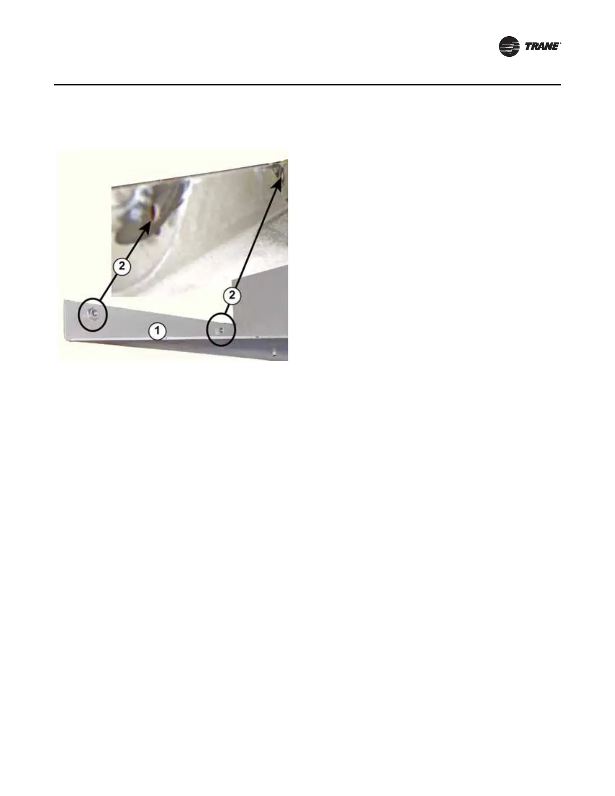
1. Inspect the Z-bracket on the chiller motor flange. If the Z-bracket is equipped with weldment
nuts, these nuts must either be ground off or drilled out to allow the 3/8-inch studs on the back
of the new drive cabinet assembly to slide into the bracket at these locations.
2. Prepare lifting equipment and rigging.
a. Depending upon the model type, a unit-mounted AFDH can weigh up to 1400 pounds.
Confirm the weight of the AFDH unit to be installed. For D-Frame units refer to Tab l e 4, p . 25 .
For E-Frame units refer to Ta bl e 5, p . 25 .
b. Verify that the intended lifting device and rigging has the capacity to safely handle the load
before hooking up to the two factory provided lifting points on top of the cabinet assembly.
c. Use the appropriate rigging techniques to ensure that the cabinet assembly will be balanced
about its center of gravity during lifting. Refer to “Recommended rigging and lifting
procedures for AFDH drive units,” p. 20.
3. Using safe lifting practices, carefully lift the cabinet and position it over the brackets on the
evaporator.
a. Bolt the angle iron clips removed from the old starter to the slots on the bottom of the drive
4. Slowly lower the cabinet until the clips make contact with the evaporator brackets but do not
place the full weight of the cabinet onto the brackets at this time. Keep tension on the lift rigging
to support the weight of the cabinet.
a. Adjust the angle iron clips as necessary at the base of the cabinet until the back of the cabinet
is level and lined up against the Z-bracket, then attach the cabinet to the bracket using the
kit hardware provided.
b. Secure the angle iron clips to the evaporator brackets with the bolts previously used to
secure the old starter panel to them.
c. Ensure that all nuts are properly tightened at all cabinet mounting points.
5. Confirm that the drive is firmly attached to all brackets and is stable before slowly lowering the
lifting device to slacken the rigging and remove it from the lifting points.
Figure 19. Removal of Z-bracket weldment nuts
1. Z-bracket
2. Weldment nuts (4 total on bracket, only 2
shown) drill out or grind off flush

 Loading...


