Installation
20 SO-SVN037A-EN
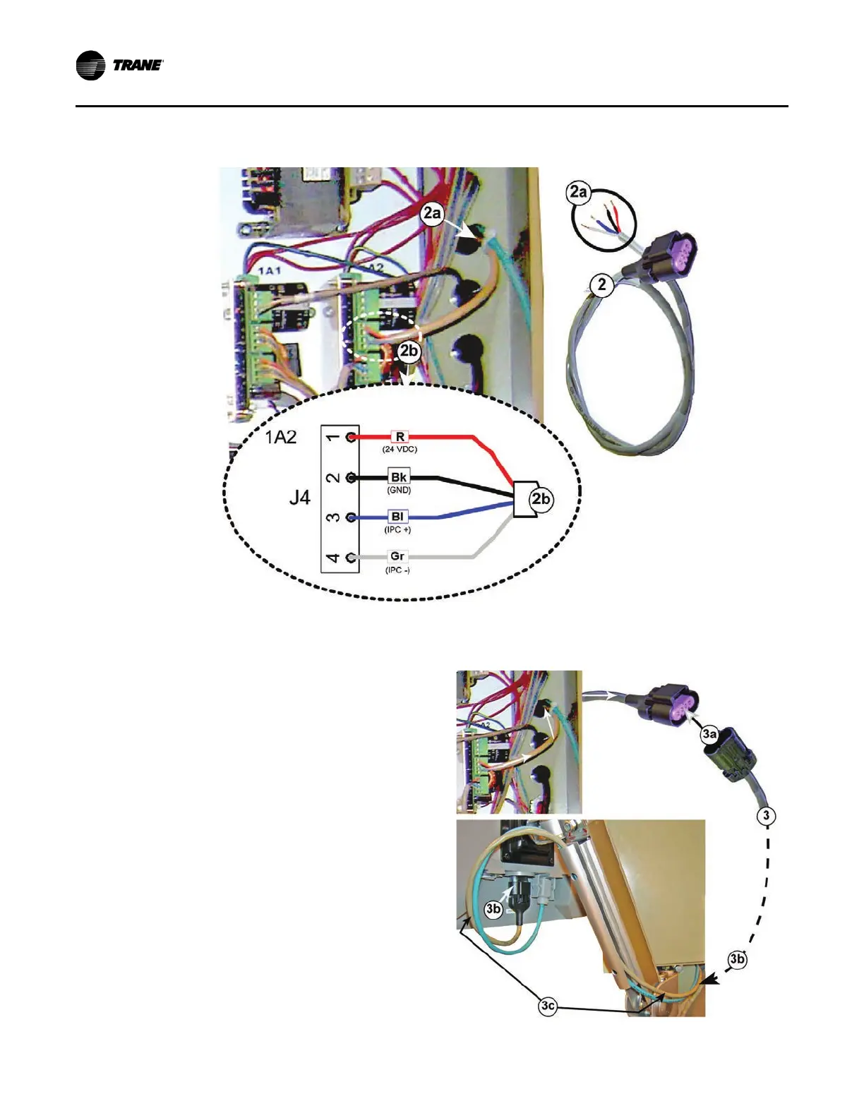
Notes:
• R. Red wire for 24 Volts direct current
• Bk. Black wire for ground
• Bl. Blue wire for IPC+ connection (not actually used by
Tracer AdaptiView but connect anyway)
• Gr. Gray wire for IPC- connection (not actually used by
Tracer AdaptiView but connect anyway)
3. Complete the power supply connection to the display using
the Male to Female wire harness extension:
a. Connect the Male end of this cable to the Female
connector on the cable installed in Step 2.
b. Route the cable harness through the wire channel on
the display arm and connect the Female end to the
Male receptacle on the display unit.
Important: Leave enough slack in the cable to allow for the
display arm to be moved through its full range
of motion without placing a strain on the cable
or the terminal connections.
Figure 29. Female to bare end wire harness install from outside cabinet in to 1A2
Figure 30. Completion of power supply connection to
the display
 Loading...
