Do you have a question about the Trane LonWorks TR200 and is the answer not in the manual?
Explains the meaning of Warning, Caution, and Notice symbols used in the manual.
Warns about the danger of adjustable frequency drives connected to line power.
Reinforces safety precautions regarding line power and communication bus.
Lists essential safety rules for working with the adjustable frequency drive.
Provides safety guidelines for installing the drive at high altitudes.
Details hazards and precautions related to unintended motor starts.
Warns about the risk of electric shock from electrical parts, even after power disconnection.
Warns that DC link capacitors remain charged after power disconnection.
Provides critical steps to follow before starting any repair work on the drive.
Explains methods for configuring the LonWorks network and addressing nodes.
Introduces the FC VSD Profile and lists input variables.
Details specific input network variables like Start/Stop, Control Word, and Reset Fault.
Introduces methods for controlling the TR200.
Explains how to select the drive configuration mode for reference.
Describes open-loop operation and speed reference transmission.
Describes closed-loop operation and scaling of feedback/reference.
Details the FC Control Profile and Control Word settings.
Lists control bits and their meanings for the FC profile.
Explains the function of specific control bits (00, 01, 02, 03, 04).
Explains bit 05 for holding output frequency.
Explains bit 06 for ramp stop/start functions.
Explains bit 07 for resetting trips.
Explains bit 08 for jog speed control.
Explains bit 09 for selecting ramp functions.
Explains bit 10 for control word validity.
Details status bits and their meanings for the FC profile.
Explains bit 00 for control readiness.
Explains bit 01 for drive readiness.
Explains bit 02 for coasting stop.
Explains bit 03 for error and trip status.
Explains bit 04 for error status without trip.
Explains bit 06 for trip lock status.
Explains bit 07 for warning status.
Explains bit 08 for speed reference matching.
Explains bit 09 for local vs. bus control.
Explains bit 10 for frequency limit status.
Explains bit 11 for operation status.
Provides a comprehensive list of TR200 parameters.
Details parameters within Group 8, focusing on control site and source.
Explains the distinction between alarms and warnings.
Lists alarm codes and their meanings.
Lists warning codes and their meanings.
Lists extended status word bits and their meanings.
| Communication Protocol | LonWorks |
|---|---|
| Frequency Range | 50/60 Hz |
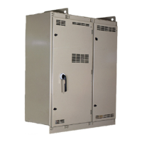
| Enclosure Rating | NEMA 1 |
| Category | Industrial Equipment |
| Operating Temperature Range | -10°C to 50°C |
| Display | LCD |
| Mounting | Wall Mount |
| Drive Type | Variable Frequency Drive |
| Control Method | Sensorless Vector Control |
| Type | Variable Frequency Drive |
| Humidity Range | 5% to 95% (non-condensing) |


 Loading...