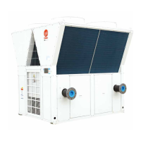
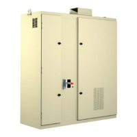
MODULE MODULE
Description of ground terminal for RS485 control wire
•
Forbid to be connected to the high voltage 220V ground wire terminal of the iron sheet for
the electric control box.
•
RS485 ground port G is the ground terminal of the DC power supply for the electric control
panel.
Installation requirements of RS485 communication cable
1. Requirements of communication line: RS485 wiring must be AWG 18-22, the line diameter
must be larger than 0.75 mm2, the twisted pair shall be provided with the shielding layer, and
the twist distance shall not be more than 5 cm. It is recommended to use BELDEN, 5320FE.
2. Requirements of hand by hand wiring: each system module is provided with two terminals A
and B for RS485 connection, and the module of the outdoor unit is provided with the terminal
G besides the terminals A and B for connecting the shielding layer of the communication
line. The shielded twisted pair must be wired hand by hand without star connection, i.e. 1 is
connected to 2, 2 is connected to 3, and 3 is connected to 4, which is correct; if 1 is connected
2, 2 is connected to 3, and 2 is connected to 4, it will be wrong.
3. Wiring requirements of shielding layer: after being twisted, the shielding layer is covered
with the adhesive tape to prevent from being connected with 220V ground wire, and one end
of the shielding layer is connected with the earth point G of the outdoor unit control cabinet.
When the module of the outdoor unit is connected, the shielding layer is connected to the
terminal G. Forbid to be connected to 220V ground wire terminal of the iron sheet for the
electric control box.
4. When the network is unstable, install the terminator (shipped with the Centralized Controller)
to the communication ports A and B of the last unit of the network.
Function of centralized controller
Introduction
Single-unit operation: the centralized controller can operate any single unit on the network, for
example, start up and shut down, change the mode, change the set temperature and so on.
Multi-unit operation: the centralized controller can start up and shut down all connected units on

 Loading...


