8 ACC-SVN240C-EN
Installation
FIADAST001*/002*
Field Installed DAS Assembly and Installation
This section covers installation of DAS not installed in the rooftop unit at the factory.
Note: DAS installation must be performed prior to installation of equipment at the job site.
Below installation Instructions are generic and Table 9, p. 12 must be used to determine the correct DAS configuration.
1. Turn OFF the main power disconnect switch.
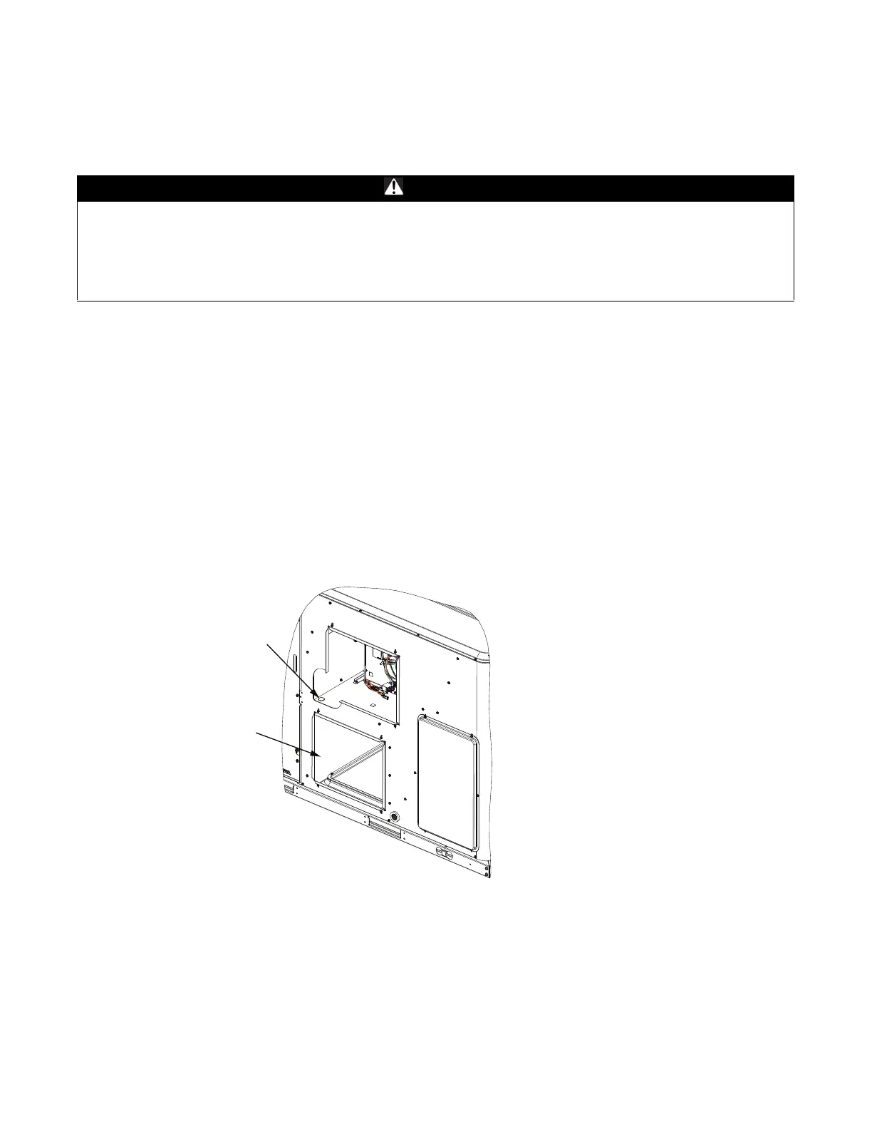
2. Remove the rear access panel directly above the horizontal supply duct cover and remove the plug from DAS tube hole on
the panel. See Figure 1.
3. Remove the supply air duct cover on the rear side of the unit Figure 1.
4. Prepare two separate sub-assemblies with tubes, brackets and screws provided based on unit model number. Refer to Ta b le 9 ,
p. 12.
5. Once assemblies are ready, insert the vertical tube (assembly 1) through the DAS hole from the bottom and then connect the
second tube assembly to the first tube assembly using a screw. See Figure 2, p. 9 and Figure 3, p. 9.
6. Close any unused screw holes on the tubes using aluminum dot tapes.
WARNING
Hazardous Voltage!
Failure to follow instructions below could result in death or serious injury.
Power down the outdoor unit before making contact with the inverter circuit board. Follow proper lockout/tagout
procedures to ensure the power cannot be inadvertently energized.Wait for at least 15 minutes to allow the unit to
fully discharge high DC voltage. Confirm the unit is fully discharged using a CAT III or IV voltmeter rated per NFPA
70E.
Figure 1. DAS plug
Plug
Horizantal supply
duct opening