MUA-SVX006B-EN
27
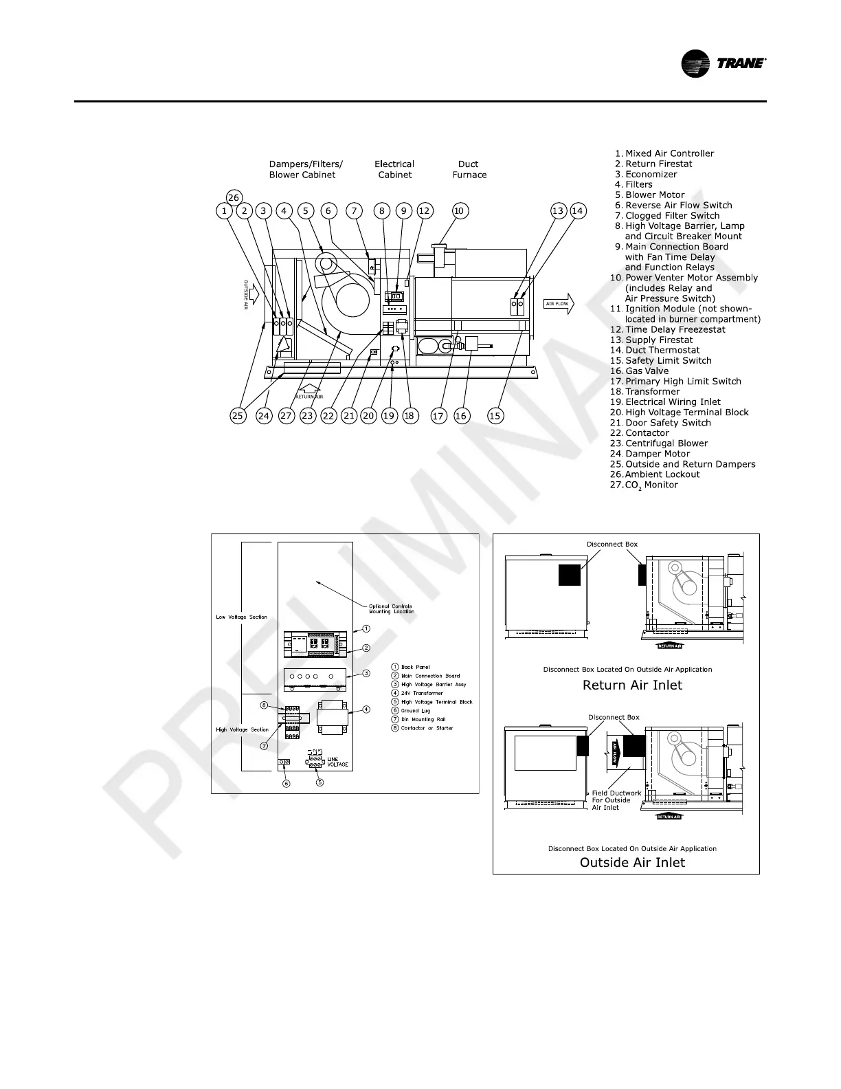
Figure 17. Make-Up Air Unit — Standard Blower Cabinet, Single Duct Furnace with Various Options Shown
Figure 18. Electrical Cabinet Figure 19. Disconnect Box Locations
DX Coil Equipped Units (Optional)
See Coil Installation/Maintenance Manual for Refrigerant Piping, Liquid and Suction Line
Components, Refrigerant Charging and Thermal Expansion Valve Adjustment. Remove coil
cabinet access door located next to blower section. Cut holes in fixed door to allow suction and
liquid line passage. Provide weatherproof seal around suction and liquid lines at piping plate
when installed.
IInnssttaallllaattiioonn