178 RT-SVX36G-EN
Maintenance
5. Remove the belt tension gauge. The small O-ring now indicates a number other than zero on
the plunger’s force scale. This number represents the force (in pounds) required to give the
needed deflection.
6. Compare the “force” scale reading (Step 5) with the appropriate “force” value listed in
Figure 91. If the “force” reading is outside the range, readjust the belt tension.
Note: Actual belt deflection “force” must not exceed the maximum “force” value shown in
Figure 91.
7. Recheck the belt tension at least twice during the first 2 to 3 days of operation. Belt tension will
decrease rapidly until the new belts are “run in”.
Table 65. Belt tension measurement and deflection ranges
Belts Cross
Section
Small P.D.
Range
Deflection Force (lbs.)
Steel Cable GripbeltsSuper Gripbelts Gripnotch
Min. Max. Min Max. Min Max
A
3.0 - 3.6 3 4 1/2 3 7/8 5 1/2 3 1/4 4
3.8 - 4.8 3 1/2 5 4 1/2 6 1/4 3 3/4 4 3/4
5.0 - 7.0 4 5 1/2 5 6 7/8 4 1/4 5 1/4
B
3.4 - 4.2 4 5 1/2 5 3/4 8 4 1/2 5 1/2
4.4 - 5.6 5 1/8 7 1/8 6 1/2 9 1/8 5 3/4 7 1/4
5.8 - 8.8 6 3/8 8 3/4 7 3/8 10 1/8 7 8 3/4
Belts Cross
Section
Small P.D.
Range
Deflection Force (lbs.)
358 Gripbelts 358 Gripnotch
Min. Max. Min Max.
5V
4.4 - 8.7 — — 10 15
7.1 - 10.9 10 1/2 15 3/4 12 7/8 18 3/4
11.8 - 16.0 13 19 1/2 15 22
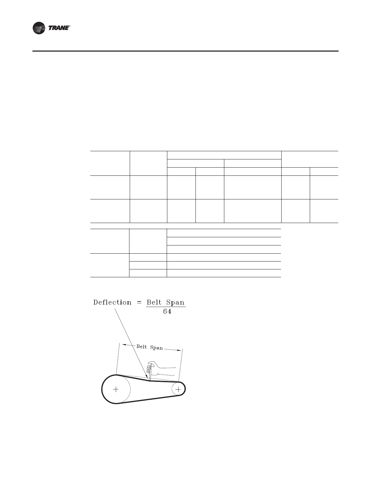
Figure 91. Belt deflection
 Loading...


