20
PKGP-SVX03D-EN
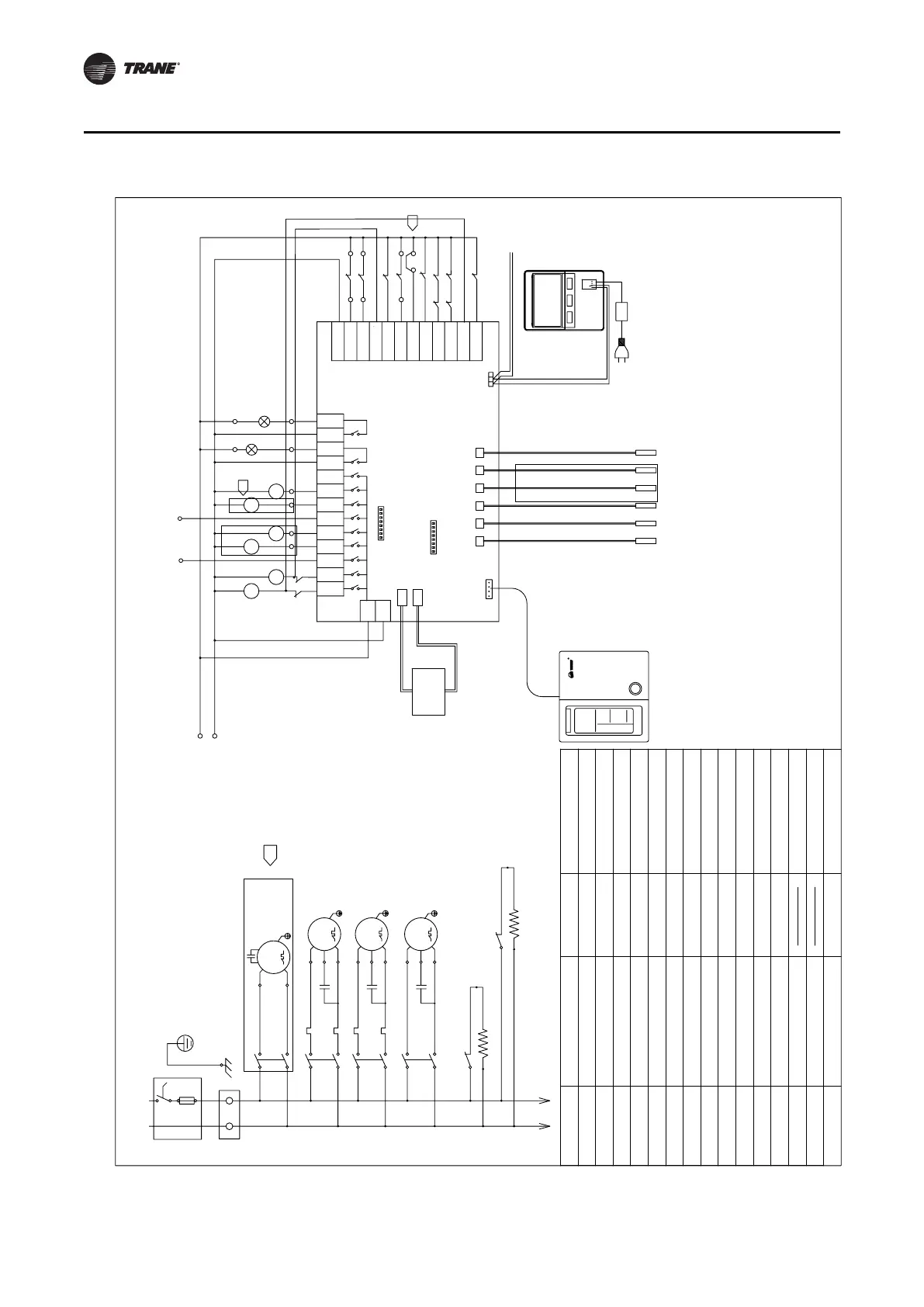
Wiring Diagram
CGAR/K0606R*
COMP2
M/FAN2
H/FAN1
A-HAT
4WV2
HE/EV1
4WV1
PUMP
COMP1
RUN_OUT
RUN_IN
AL_OUT
AL_IN
TH2
TH1
TH3
TH4
TH5
TH6
R
CON1
CON2
SW2
CN6
SW1
CN4
Technical requirement
1 For all fault inputs.the unit is normal when power on and gives an alarm when power off。
2 The flow switch is installed on site and connected between terminals U and 15.
3 Single unit the pump is optional,if customer provide pump,each unit can use digital output
7 to control it ,while remove the wire jumper between terminal U and 22,connection to the
pump protection signal.
4 If use 2-valve interlock,please dial SW2-7 to "ON".
5 Control panel and main controller are optional.
Only for
heat pump
CCH2
N
L
MC2
CCH1
MC1
MOTOR
COMP1
COMP2
M
C
RD
RD
MF
MC2
RD
BK
BK
WH
Cfr
RD
BKBK
FAN
M
1~
Cr2
BU
YEYE
1~
S
M
R
MC1
RD
BK
BK
MP
RD
Cr1
BU
YEYE
1~
S
M
R
YE
1~
PUMP
C
TB1
RD RD
Cpr
L
N
OL1
OL2
220VAC
L
N
36
21
8
7
6
N
10
N
11
345
L
N
Auxiliary
electrical
heater
Plate heat
exchange
electric
heater
ACD_OD_CO1
(Double compressor)
Controller
water inlet sensor
water outlet sensor
Discharge sensor 1
Defrost sensor 1
Defrost sensor 2
Discharge sensor 2
Heat pump only
21
19
20
18
LP1
OVF1
17
14
13
15
N
25
LP2
FS
4WV1
MC2
MP
AL
RUN
4WV2
MF
MC
1
EG-SAVE
12
C/H
16
OL2
OL1
22
HP1
HP2
0V-PUMP
FL0W
0V-C0MP1
FREZ/LP2
VHT/HP2
N-COM
EN-SAVE
C/H
HP1
LP1
0V-C0MP2
0V-FAN
YE
YE
YE
YE
3
PS1
PS2
TO Controller
Alarm indicator
Running indicator
Wiring Diagram
power supply of the main controller
Main controller
(option)
Communication with other units
Control panel
(Indoor installation)
option
Factory wiring
EN-SAVE
RUN-OUT/IN
CCH
PUMP
AL-OUT/IN
N-COM
H/FAN
HT/EV1
A-HAT
COMP
MC
MF
MP
Fan Overload
OVF
Reversing Valve
4WV
OL
Compressor Overheat
LP
TB
HP
Low pressure switch
Terminal Blocks
High pressure switch
FS
OVP
Flow Switch
Pump Overload
C/H
On-site wiring
OV-COMP
Compressor Overload
PS
Medium-pressure switch
Description
Description
Name Name
Pump Contactor
Compressor Contactor
Fan Contactor
Crankcase Heater
Compressor
Water Circuit Based
Electrical Heating Control
Plate Heat Exchanger Heater
Water Pump
Fan Motor
Alarm Output/Input
Common Neutral Line
Run Output/Input
Energy Saving/2-Way Valve
Interlock
Outer Cool/Heat Setting
CGAR/K0606R*
220V~/50Hz
L
N
BA
+12VGND
CN1
ABG
3
3
Transformer
RD
WH