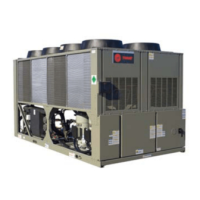
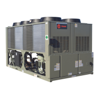
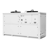
Do you have a question about the Trane CGAD020C and is the answer not in the manual?
Defines the basic model identifier.
Specifies the tonnage capacity of the unit.
Details power supply and command voltage options.
Indicates the type of refrigerant used.
Describes available piping configurations.
Lists available control modules.
Specifies the type of coil used.
Details the type of expansion valve.
Refers to optional accessories.
Provides general specifications for models 20-90 TR.
Details compressor specifications.
Lists evaporator specifications.
Provides condenser specifications.
Lists fan specifications.
Presents overall unit data.
Illustrates a unit selection process with data and calculation.
Provides formulas for calculating evaporator flow.
Important note regarding flow limits.
Important note regarding minimum leaving water temperature.
Guidance on selecting appropriate unit capacity.
Recommendations for optimal unit positioning.
Methods for reducing sound transmission.
General considerations for unit placement.
Specifies vertical clearance requirements.
Specifies side clearance requirements.
Details clearance between units.
Installation advice for walled locations.
Details on installing evaporator hydraulic piping.
Instructions for connecting the evaporator drain.
Requirements for installing thermometers and manometers.
Explains the components in Fig. 01.
Guidelines for flow-switch installation.
Importance of water treatment for equipment.
Graph for evaporator pressure drop for 20-60 ton units.
Conversion factors for units.
Graph for evaporator pressure drop for 70-90 ton units.
Graph for evaporator pressure drop for 100-120 ton units.
Unit conversion table.
Graph for evaporator pressure drop for 150 ton units.
Factors for ethylene glycol performance.
Correction factors for altitude.
Factors for propylene glycol performance.
Freezing points for antifreeze solutions.
Performance data for R-22 at 4°C condenser air temp.
Performance data for R-22 at 5°C condenser air temp.
Performance data for R-22 at 6°C condenser air temp.
Performance data for R-22 at 7°C condenser air temp.
Performance data for R-22 at 8°C condenser air temp.
Performance data for R-22 at 9°C condenser air temp.
Performance data for R-22 at 10°C condenser air temp.
Performance data for R-407C at 4°C condenser air temp.
Performance data for R-407C at 5°C condenser air temp.
Performance data for R-407C at 6°C condenser air temp.
Performance data for R-407C at 7°C condenser air temp.
Performance data for R-407C at 8°C condenser air temp.
Performance data for R-407C at 9°C condenser air temp.
Performance data for R-407C at 10°C condenser air temp.
Electrical data for 60 Hz models.
Electrical data for 50 Hz models.
Details the CH530 controller and DynaView module.
Describes safety features of the controller.
Options for external control integration.
Remote unit activation/deactivation.
Interlock for water pump flow.
Controller output for water pump activation.
Control for hot gas bypass valve.
Emergency unit shutdown functionality.
Additional control options available.
Remote adjustment of chilled water setpoint.
Programmable relays for status signaling.
Controls for ice making and demand.
Interface for Trane Tracer Summit system.
Overview of operational protection features.
Internal compressor motor protection.
Phase sequence and presence monitoring.
Protection via overload relays.
Optimizes compressor start sequences.
Flow switch for evaporator water monitoring.
Prevents freezing by monitoring water temperature.
Monitors and limits high discharge pressure.
Restricts operation based on low suction pressure.
Controls operation based on outdoor air temp.
Auto-adjusts setpoint based on ambient temp.
Limits capacity during startup to prevent overload.
Operational adjustments for cold environments.
Procedures for operational recovery and refrigerant service.
Overview of integrated HVAC control systems.
Building management system for chillers.
Lists applications for Tracer Summit.
Specifies necessary options for integration.
Lists required hardware and software.
Controls for ice making mode.
Other optional features.
Relays for signaling unit status.
Trane's expertise in chiller automation.
Strategies for optimizing energy efficiency.
Importance of providing operational information.
Procedures for emergency response.
Covers chiller management documentation.
Capabilities of integrated comfort systems.
Dimensional drawings for CGAD 020C model.
Notes on vibration insulators and units.
Top view diagram of fans for CGAD 020C.
Dimensional drawings for CGAD 025C/030C models.
Top view diagram of fans for CGAD 025C/030C.
Notes on vibration insulators and units.
Dimensional drawings for CGAD 040C model.
Top view diagram of fans for CGAD 040C.
Notes on vibration insulators and units.
Dimensional drawings for CGAD 050B/060C models.
Top view diagram of fans for CGAD 050B/060C.
Notes on vibration insulators and units.
Dimensional drawings for CGAD 070C model.
Top view diagram of fans for CGAD 070C.
Notes on vibration insulators and units.
Dimensional drawings for CGAD 080C/090C models.
Top view diagram of fans for CGAD 080C/090C.
Notes on vibration insulators and units.
Dimensional drawings for CGAD 100C model.
Top view diagram of fans for CGAD 100C.
Notes on vibration insulators and units.
Dimensional drawings for CGAD 120C model.
Top view diagram of fans for CGAD 120C.
Notes on vibration insulators and units.
Dimensional drawings for CGAD 150C model.
Top view diagram of fans for CGAD 150C.
Notes on vibration insulators and units.
Diagrams for maintenance and air circulation clearances.
Additional diagrams for clearances.
Details on shell and tube evaporators.
Information on coil-type condensers.
Diagram of the shell and tube evaporator.
Diagram showing condenser air flow.
Specifications for refrigerating lines.
Components of cooling circuits.
Benefits and features of scroll compressors.
Diagram of a liquid sightglass.
Diagram of an expansion valve.
Comparison of scroll vs. reciprocating compressors.
Diagram of a drier filter.
Explanation of the scroll compressor compression cycle.
Detailed diagram of a scroll compressor.
Table of general dimensional data for models.
Overall dimensional drawing of the unit.
Notes regarding length and floor area measurements.
| Model | CGAD020C |
|---|---|
| Refrigerant | R-410A |
| Compressor Type | Scroll |
| Voltage | 208-230/460 V |
| Phase | 3 |
| Type | Air-Cooled Chiller |
| Cooling Capacity | 20 Tons |


