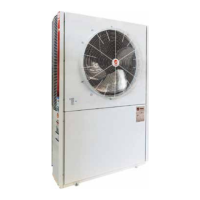
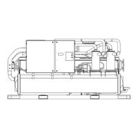
22
PKGP-SVX03D-EN
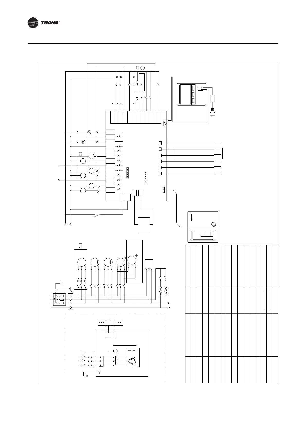
Wiring Diagram
CGAR/K1005R* 1205R/1505R*/2005R*
Wiring Diagram
500003110100
Factory wiring
EN-SAVE
RUN-OUT/IN
CCH
PUMP
AL-OUT/IN
N-COM
H/FAN
HT/EV1
A-HAT
COMP
MC
MF
MP
Fan Overload
OVF
Reversing Valve
4WV
HTR
HS
HC
Heater Protector
Water Circuit Heater
Heater Contactor
LP
TB
HP
Low pressure switch
Terminal Blocks
High pressure switch
FS
OVP
Flow Switch
Pump Overload
RFS
Phase Sequence Controller
C/H
On-site wiring
OV-COMP
Compressor Overload
Heater
TO Controller
option
3.
0V-PUMP
FL0W
0V-C0MP1
FREZ/LP2
VHT/HP2
N-COM
EN-SAVE
C/H
RFS
HP1
LP1
HP1
LP1
FS
LP2
0V-C0MP2
0V-FAN
OVF1
OVF2
YE YE
YE YE
4
MP
RUN
MC2
MF
AL
MC1
4WV1
4WV2
HP2
PS1
PS2
PS
Medium-pressure switch
Water loop heater (option)
Alarm indicator
Running indicator
power supply of the main controller
Main controller
(option)
Communication with other units
Control panel
(Indoor installation)
Description
Description
Name
Name
Pump Contactor
Compressor Contactor
Fan Contactor
Crankcase Heater
Compressor
Water Circuit Based
Electrical Heating Control
Plate Heat Exchanger Heater
Water Pump
Fan Motor
Alarm Output/Input
Common Neutral Line
Run Output/Input
Energy Saving/2-Way Valve
Interlock
Outer Cool/Heat Setting
TH2
TH1
TH3
TH4
CON1
CON2
TH5
TH6
OVP
SW2
CN6
R
SW1
HT/EV1
4WV1
COMP1
COMP2
H/FAN1
M/FAN2
RUN-OUT
PUMP
4WV2
A-HAT
RUN-IN
AL-OUT
AL-IN
RD
WH
CN4
Technical requirement
1 For all fault inputs.the unit is normal when power on and gives an alarm when power off。
2 The flow switch is installed on site and connected between terminals U and 15.
3 Single unit the pump is optional,if customer provide pump,each unit can use digital output
7 to control it ,while remove the wire jumper between terminal U and 22,connection to the
pump protection signal.
4 CGAR/K1505/2005 have the fan2 overload protect switch.
5 If use 2-valve interlock,please dial SW2-7 to "ON".
6 Control panel and main controller are optional.
Only for
heat pump
380V~/50Hz/3φ
B
A
C
BA
+12VGND
CN1
ABG
CGAR/K1005R*
CGAR/K2005R*
CGAR/K1205R*
380V~/50Hz/3φ
HS2
HS1
HTR
HC
HC
TB2
TB2
N
3
N
3
TB1
CCH2
CCH1
31
30
MC2
FOR CGAR/K1205,1505,2005
MC1
BK
WH
RD
3~
M
FAN
MOTOR 2
MF
M
FAN
MOTOR 1
3~
(L2)
(L3)
MC2
S
T
(L1)
R
COMP2
3~
M
(L1)
(L2)
(L3)
MC1
S
R
T
COMP1
3~
M
RD
WH
BK
MP OL
3~
M
PUMP
N
V
RFS
N
U
L
N
AC 220V~
N
12
15
18
25
16
(11)
(14)
L
17
19
14
21
ACD_OD_CO1
3
21876N10 N11345
6
22
main manchine side
electrical heater side
RD
WH
BK
RD
WH
BK
RD
WH
BK
RD
WH
BK
RD
WH
BK
RD
WH
BK
RD
WH
BK
Auxiliary
electrical
heater
Plate heat
exchange
electric
heater
Transformer
Heat pump only
(Double compressor)
Controller
water inlet sensor
water outlet sensor
Discharge sensor 1
Defrost sensor 1
Defrost sensor 2
Discharge sensor 2
CGAR/K1505R*
EG-SAVE
C/H
UV
W
TB1
W
NUV
3
3