Do you have a question about the Trane Mitsubishi Electric CITY MULTI Series and is the answer not in the manual?
| Brand | Trane |
|---|---|
| Model | Mitsubishi Electric CITY MULTI Series |
| Category | Air Conditioner |
| Language | English |
Specific safety advice for R410A refrigerant, including piping, oil, tools, and handling.
Detailed safety precautions for R410A refrigerant handling and system operation.
Guidelines for performing service operations on the unit, including refrigerant recovery.
Procedures and precautions for charging refrigerant into the system.
Lists and specifications of tools required for R410A refrigerant service.
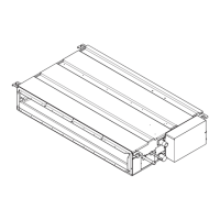
Identification of major components of the indoor unit with labels.
Comparison of functions supported by different wired remote controller models.
Explanation of the wired remote controller's display and button layout.
Detailed explanation of each button's operation on the remote controller.
Explanation of the detailed display mode of the remote controller interface.
Explanation of the simplified display mode of the remote controller interface.
Definitions and meanings of various icons shown on the remote controller display.
Menu options for controlling unit operation modes like vane, power, and sensors.
Options for setting various timers for unit operation.
Settings related to energy saving modes and restrictions.
How to check and display error codes and filter status.
Access to test runs, maintenance info, and function settings.
Detailed settings for vane, high power, comfort, and sensor functions.
Settings for ON/OFF, Auto-Off, Weekly, and Silent timers.
Details on restriction, auto return, and schedule settings.
Configuration for controllers, clock, display, and operation modes.
Function to change the maintenance password and initialize the controller.
Explanation of the display layout, central control, and error indicators.
Table detailing electrical and physical specifications for various models.
Lists model names and details on cooling/heating performance and power.
External dimensions, weight, and grille specifications.
Details on the fan type, static pressure, and motor specifications.
Specifications for refrigerant pipe diameters and drain pipe size.
Table showing sound pressure levels for different models and fan speeds.
NC curves showing sound levels across frequencies for specific models.
NC curves showing sound levels across frequencies for specific models.
NC curves showing sound levels across frequencies for specific models.
Specifications for temperature thermistors, fuses, fan motors, and vane motors.
Specifications for the drain pump, float switch, and linear expansion valve.
Guide for setting air outlet directions and switch configurations.
DIP switch settings for ceiling height and air outlet configuration.
Diagrams showing dimensions for branch duct holes and installation notes.
Visual guide for fresh air intake hole dimensions and placement.
Wiring instructions for connecting a duct fan with the indoor unit.
Characteristics of fresh air intake and static pressure for specific models.
Guide on interpreting the static pressure vs. airflow rate graphs.
Important notes regarding grille selection and installation considerations.
Specifications for suspension bolts and model capacity listings.
Diagram of electrical connections with important service warnings.
Table showing SW2 settings for different model capacities.
Symbols and their meanings used in the wiring diagram.
Diagram showing refrigerant flow and specifications for gas and liquid pipes.
Detailed control logic and operation for the cooling mode.
Instructions for operating the unit in cooling mode using the remote.
Control logic for the drain pump and float switch operation.
Control of vane position during operation.
Instructions for operating the unit in dry mode using the remote.
Specific control logic and parameters for dry operation.
Instructions for operating the unit in fan mode using the remote.
How fan speed is set and drain pump operates in fan mode.
Instructions for operating the unit in heat mode using the remote.
Specific control logic and parameters for heat operation.
Details on hot adjust mode and fan behavior in thermo-OFF.
Control logic for the drain pump during heat operation.
Instructions for operating the unit in auto mode using the remote.
Logic for switching between cooling and heating modes.
Drain pump operation when the unit is stopped.
Procedures for checking the resistance of various electrical components.
Checking resistance of thermistors and continuity of motors.
Graph showing thermistor resistance versus temperature.
How the linear expansion valve functions and its control.
Table showing output signals and their effect on valve operation.
Common issues with the linear expansion valve and their solutions.
Procedures for diagnosing issues with the DC fan motor.
Steps to verify electrical connections and power supply for the fan motor.
Explains the functions set by DIP switch SW1.
How SW2 is used to set the unit's capacity code.
Details the functions controlled by DIP switch SW3.
Setting the 1s and 10s digits for address configuration.
Settings for the connection number, particularly for R2 series.
How to set the pair number for wireless remote controllers.
Procedure to activate test run for drain pump and fan motor.
Diagram showing test points on the indoor controller board.
General steps for disassembling the unit.
Step-by-step guide to remove the intake grille, filter, and electrical cover.
Procedure to remove the main electrical box.
Steps to remove the turbo fan assembly.
Detailed steps for removing the turbo fan motor.
Steps to remove the main unit grille.
Procedure to remove the drain pan.
Steps to remove temperature sensors, drain pump, and float switch.
Procedure to remove the heat exchanger assembly.
Details on removing coil supports for different models.